
The diagram of the non-contact ignition system is shown in fig. 9-17. In this system, the power circuit of the primary winding of the ignition coil is interrupted by a powerful transistor in the electronic switch 5. The control pulses to the switch are supplied from a proximity sensor located in the ignition distributor 6.
The initial setting angle of the ignition timing for adjusting the ignition timing is 1°±1°.
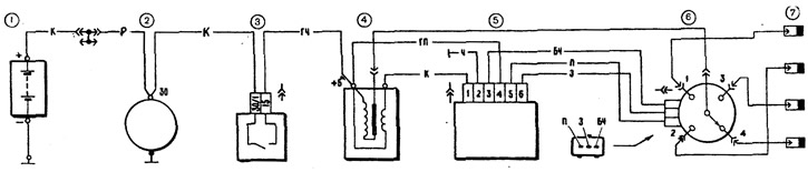
Pic. 9-17. Scheme of a contactless ignition system: 1 - battery; 2 - generator; 3 - ignition switch; 4 - ignition coil; 5 - switch; 6 - sensor-distributor ignition; 7 - spark plugs
Warnings:
- The vehicle adopts a high energy ignition system with a wide application of electronics. Therefore, in order not to get injured and not to disable the electronic components, the following rules must be observed.
- Do not touch ignition system components while the engine is running (switch, ignition coil and high voltage wires), and even more so disconnect high-voltage wires.
- Do not start the engine using the spark gap and do not check the operation of the ignition system «for a spark» between the spark plug wire ends and ground. All this can lead to burnout of high-voltage parts and failure of the ignition system.
- Do not run the low voltage wires of the ignition system in the same bundle as the high voltage wires.
- Monitor the reliability of the connection to the commutator ground through the fastening screws. This affects its smooth operation.
- With the ignition on, do not disconnect the wires from the battery terminals and do not disconnect the plug connector from the switch, as this may cause increased voltage on individual elements of its circuit and it will be damaged.
- After servicing or repairing the vehicle, before starting the engine, make sure that the high-voltage wires are securely connected to the ignition coil and spark plugs.
The following are malfunctions related to the original components of the non-contact ignition system. For other faults, see chapter «Ignition system».
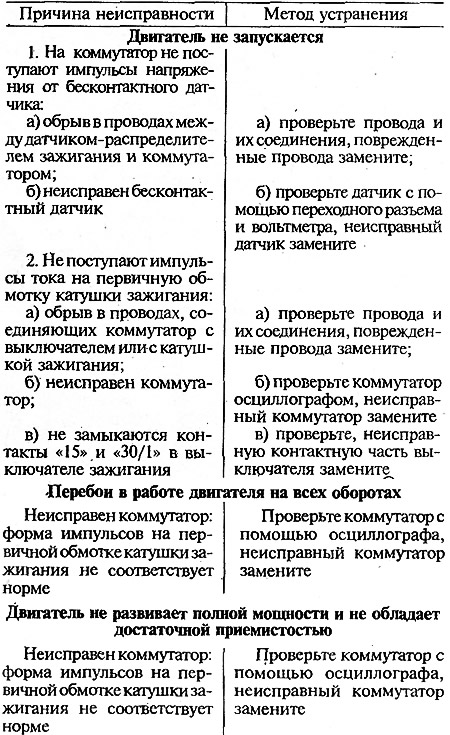
Possible malfunctions of the non-contact ignition system, their causes and methods of elimination
Ignition distributor
In the non-contact ignition system of the 21213 engine, the ignition distributor sensor type 3810.3706 is used. It differs from the ignition distributor 30.3706-02 in that instead of a cam on the roller there is a steel screen 18 (pic. 9-18) with four slots, and instead of the contacts of the interrupter, a microelectronic contactless sensor 20 is installed, which operates on the basis of the Hall effect.
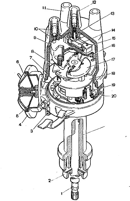
Pic. 9-18. Sensor-distributor ignition 3810.3706: 1 - roller; 2 - oil slinger; 3 - plug connector; 4 - housing of the vacuum regulator; 5 - diaphragm, 6 - vacuum regulator cover; 7 - thrust of the vacuum regulator; 8 - base plate of the centrifugal regulator; 9 - ignition distributor rotor; 10 - side electrode with a terminal; 11 - cover; 12 - central electrode with terminal; 13 - coal of the central electrode; 14 - resistor; 15 - outer contact of the rotor, 16 - centrifugal regulator plate; 17 - weight; 18 - screen; 19 - contactless sensor support plate; 20 - proximity sensor; 21 - ignition distributor sensor housing.
Voltage is removed from the output of the proximity sensor if there is a screen in its gap. If there is no screen in the gap, then the voltage at the output of the sensor is close to zero.
Checking the sensor-distributor of ignition on the stand
The ignition distributor 3810.3706 is checked by the same method as the ignition distributor 30.3706-02. To check, make connections to the ignition coil, battery and switch in the same way as the car ignition system diagram (see fig. 9-17).
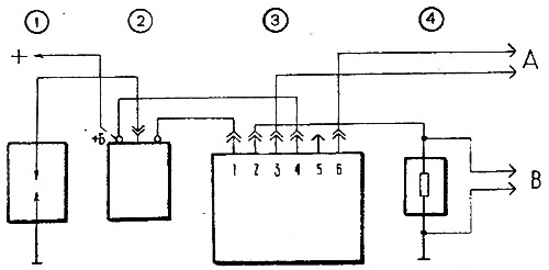
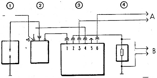
To measure the characteristics of the centrifugal and vacuum ignition timing regulators, make connections with the switch on the stand according to fig. 9-19. Conclusion «4» switch 1 connect to terminal «+» stand, output «1» - with clamp «breaker» stand, and conclusions «3», «5» and «6» — with the sensor-distributor of ignition.
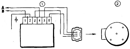
Pic. 9-19. Scheme for characterization of the ignition distributor sensor on the stand: 1 - switch; 2 - sensor-distributor ignition; A - to the terminal «+» stand; B - to terminal «breaker» booth
The method of characterization is the same as that of the ignition distributor 30.3706-02. The characteristics of the centrifugal and vacuum ignition timing controllers for the ignition distributor 3810.3706 are shown in fig. 9-20 and 9-21.
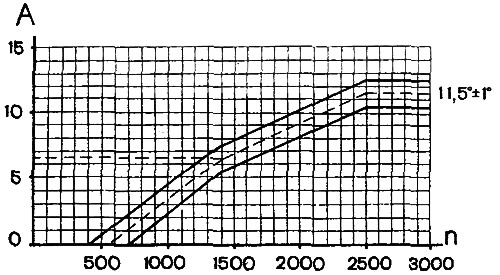
Pic. 9-20. Characteristics of the centrifugal regulator of the sensor-distributor of ignition: A - ignition timing, deg; n - frequency of rotation of the roller of the sensor-distributor of ignition, min-1
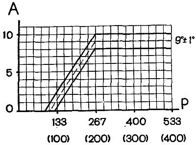
Pic. 9-21. Characteristics of the vacuum regulator of the sensor-distributor of ignition: A - ignition timing, deg; Р - rarefaction hPa (mmHg Art.)
Checking the proximity sensor
On the sensor-distributor of ignition removed from the engine, the sensor can be checked according to the diagram shown in fig. 9-22, with a supply voltage of 8-14 V.
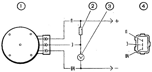
Pic. 9-22. Scheme for checking the proximity sensor on the removed ignition distributor sensor: 1 - sensor-distributor ignition; 2 - resistor 2 kOhm; 3 - voltmeter with a scale limit of at least 15 V and an internal resistance of at least 100 kOhm; 4 - view of the plug connector of the ignition distributor
Slowly rotating the ignition distributor shaft, measure the voltage at the sensor output with a voltmeter. It should change sharply from the minimum - no more than 0.4 V, to the maximum - no more than 3 V lower supply voltage.
On the car, the sensor can be checked according to the diagram shown in fig. 9-23. Adapter connector 2 with a voltmeter is connected between the plug connector of the ignition distributor and the connector of the wire bundle. Turn on the ignition and, slowly turning the crankshaft with a key, check the voltage at the sensor output with a voltmeter. It must be within the above limits.
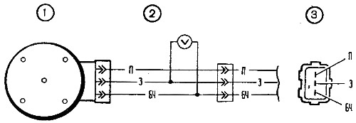
Pic. 9-23. Scheme for testing a proximity sensor on a car: 1 - sensor-distributor ignition; 2 - adapter with a voltmeter having a scale limit of at least 15 V and an internal resistance of at least 100 kOhm; 3 - view of the plug connector of the ignition distributor
Switch
In a contactless ignition system, switches of the type 3620.3734, HIM-52 or BAT10.2 can be installed (the last two are Hungarian-made).
The switch is checked using an oscilloscope and a square-wave generator according to the circuit shown in fig. 9-24. The output impedance of the generator should be 100-500 ohms. It is desirable to use a two-channel oscilloscope. The 1st channel is for generator pulses, and the 2nd is for commutator pulses.
Pic. 9-24. Scheme for checking the switch: 1 - arrester; 2 - ignition coil, 3 - switch; 4 - resistor 0.01 Ohm±1%, not less than 20 W; A - to the generator of rectangular pulses; B - to the oscilloscope
On terminals «3» and «6» The commutator receives square-wave pulses imitating sensor pulses. The pulse frequency is from 3.33 to 233 Hz, and the duty cycle (ratio of period to pulse duration T/Ti) equals 1.5. Maximum voltage Umax - 10 V, and the minimum Umin no more than 0.4 V (pic. 9-25 II). For a working switch, the shape of the current pulses must correspond to the oscillogram I.
Pic. 9-25. The shape of the pulses on the oscilloscope screen: I - commutator impulses; II - generator pulses; A - current accumulation time; V - maximum current
For switch 3620.3734 with supply voltage 13.5+0,1 V magnitude of current (IN) should be 7.5-8.5 A. Current accumulation time (A) not standardized.
For HIM-52 switch at supply voltage (13,5±0,2) The current value should be 8-9 A, and the accumulation time should be 8-10.5 ms at a frequency of 25 Hz. For the BAT10.2 switch at the same voltage and frequency, the current strength is 7-8 A, and the accumulation time is 5.5-7.5 ms.
If the shape of the commutator pulses is distorted, then there may be interruptions in the neoplasm or it may occur with a delay. The motor will overheat and not develop its rated power.
Ignition coil
For ignition coil 27.3705, used in a non-contact ignition system, the resistance of the primary winding at 25°C is (0,45±0,05) Ohm, and the secondary winding - (5±0,5) kOhm
Spark plug
Contactless ignition system uses A17DVR, or FE65PR, or FE65CPR spark plugs (the last two types are Yugoslavian production). Spark plugs have a built-in noise suppression resistor with a resistance of 4 - 10 kOhm.
The gap between the electrodes of the spark plugs is 0.7-0.8 mm. The candle is considered defective if sparking between the electrodes of the candle begins at a pressure below 0.3 MPa (3 kgf/cm2).
High voltage wires
In the contactless ignition system, high-voltage wires of the PVVP-8 type are used (Red) with distributed resistance (2000±200) Ohm/m or PVPPV-40 (of blue color) with distributed resistance (2550±270) ohm/m