




Contents: Service brake system ↓ Parking brake system ↓
Braking systems are designed to reduce speed, stop and hold the vehicle in place when parked.
The service brake system reduces the speed of movement and stops the vehicle, and the parking brake system keeps the vehicle in place when parked.
The car is equipped with two braking systems: service and parking. In case of damage to the service system, the car is stopped by the serviceable part (brake circuit of the front or rear wheel brakes) service brake system. Each brake system consists of brake mechanisms (brakes) and a brake drive.
Service brake system
The service brake system acts on all wheels of the vehicle and is driven by pedal 7 (Fig. 45) when pressed with the foot. The service brake system includes front 1 and rear 12 brake mechanisms and a hydraulic dual-circuit drive: primary 4 (front brakes) and secondary 5 (rear brakes).
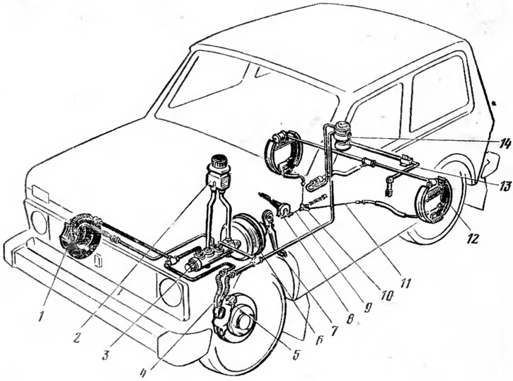
Fig. 45. Brake system diagram:
1 - front brake mechanism; 2 - brake reservoir: 3 - master brake cylinder; 4 - primary circuit; 5 - secondary circuit; 6 - vacuum booster: 7 - brake pedal; 8 - parking brake lever; 9 - Front parking brake cable; 10 - rear cable guide; 11 - rear parking brake cable; 12 - rear brake mechanism; 13 - pressure regulator lever; 14 - pressure regulator.
The front brake mechanisms (Fig. 46) are disc brakes. They are located in the front wheels of the car. The rotating and rubbing parts of the brake mechanisms are the brake discs.

Fig. 46. Front brake mechanism:
a - assembled; b - details;
1 - brake cylinder block; 2 - brake pads; 3 - caliper clamping lever; 4 - brake shield; 5 - axis of the clamping lever; 6 - brake shoe guide; 7 - brake caliper; 8 - wheel and brake disc mounting stud; 9 - wheel hub; 10 - brake disc; 11 - caliper protective cover; 12 - piston; 13 - guide bevels; 14 - spring of the pressure lever; 15 - protective cap; 16 - rubber sealing ring.
The cast iron brake disk 10 is attached with studs 8 to the hub 9 of the front wheel. From the front side in the direction of the vehicle's movement, the brake disk is covered by a support 7, which is a U-shaped bracket with guide bevels 13, which are clamped between the guide 6 of the brake shoes and the pressure levers 3, which also have guide bevels. Such a support fastening ensures its movement during braking along the guide bevels of the levers 3 and the guide 6. The support has a protective casing.
In the guide 6, attached to the steering knuckle, the brake shoes 2 with friction linings are placed. By means of axes 5, two clamping levers 3 of the support are pivotally connected to the brake shoe guide. In the brake support 7, the block of brake cylinders 1 is pressed. In the block there are three cylinders, of which the middle and lower ones are connected to each other by a channel and are connected to the drive circuit of the front brakes, and the upper cylinder is connected to the drive circuit of the rear brakes. In each cylinder, a piston 12 is installed and in the groove of the cylinder - a rubber sealing ring 16. This ring not only seals the piston in the cylinder, but also ensures, due to its elasticity, the removal of the piston from the shoe after braking. Thus, the rubber sealing rings 16 provide automatic adjustment of the gap between the brake disc and the brake shoes. The pistons of all cylinders come into contact with the inner brake shoe and are covered on its side by rubber protective caps 15. On the inner side, the front brake mechanism is covered by a brake shield 4.
When braking, under the action of the fluid pressure in the hydraulic drive, the pistons move the inner brake shoe relative to the guide 6 and the caliper 7 and press it to the brake disc 10. At the same time, under the action of the fluid pressure, the cylinder block 1 moves together with the caliper 7 along the bevels of the guide 6 and the pressure levers 3. In this case, the caliper moves the outer brake shoe relative to the guide 6 and presses it to the brake disc. Both brake shoes are pressed to the brake disc with the same force, since the fluid pressure on the pistons and the bottom of the cylinder block is the same.
After braking stops, the fluid pressure on the pistons and the bottom of the cylinder block drops sharply. Due to the elasticity of the rubber rings 16, the pistons are moved away from the inner brake shoe, which in this case moves away from the brake disc due to its beating. At the same time, the outer brake shoe together with the caliper 7 also moves away from the brake disc as a result of its beating.
When the friction linings of the brake shoes wear out, the gap between the linings and the brake disc increases. When braking, under the action of fluid pressure, the pistons will move relative to the sealing rings 16 and take a new position in the cylinders, which will compensate for the wear of the friction linings. After braking stops, the brake shoes will move away from the brake disc by the same amount, determined by the deformation of the rubber rings 16. Thus, a constant gap between the brake shoes and the disc is automatically maintained. In this regard, during operation, the gap between the shoes and the disc of the front brake mechanism does not require adjustment.
When braking, the brake pads act on a relatively small part of the brake disc surface, leaving most of it open, which is effectively blown by air. As a result, the brake disc cools very quickly, which ensures high efficiency of the braking mechanism even with frequent braking at high speeds.
Rear brakes (Fig. 47) drum, shoe. They are located in the rear wheels of the car. The rotating parts of the brake mechanisms are the brake drums, the rubbing parts are the brake shoes, which, when braking, self-align relative to the brake drum, which ensures the greatest braking effect and more uniform wear of the friction linings.
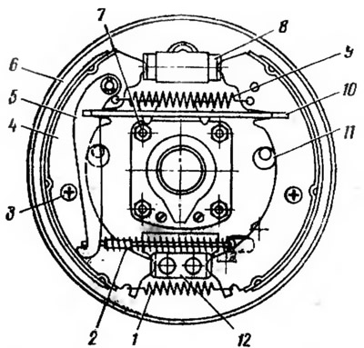
Fig. 47. Rear brake mechanism:
1, 9 - lower and upper tension springs; 2 - parking brake cable; 3 — brake shoe stop post; 4 - brake shoe; 5 - release lever; 6 - brake shield; 7 — brake shield mounting bolt; 8 - brake cylinder; 10 - spacer bar; 11 - adjusting eccentric; 12 — brake shoe support.
The stamped steel brake shield 6 is fastened with bolts to the flange of the rear axle beam. In the lower part of the brake shield, a support 12 is installed, against which the lower ends of the brake shoes 4 with friction linings rest. The upper ends of the shoes are in contact with the pistons of the wheel brake cylinder 8. The lower and upper ends of the brake shoes are pulled together by springs 1 and 9. The lateral displacement of the shoes is limited by stands 8 with springs, which press the shoes to the brake shield. Such fastening of the brake shoes on the brake shield allows them to freely self-align relative to the brake drum during braking. The ribs of the brake shoes rest against eccentrics 11, fixed to the brake shield. With the help of these eccentrics, the gap between the shoes and the brake drum is adjusted. The brake drum is fastened with bolts to the flange of the axle shaft.
When braking, under the action of the fluid pressure in the brake drive, the pistons of the wheel brake cylinder press the shoes to the brake drum. In this case, the tension spring 9 of the shoes is stretched. After braking stops, the fluid pressure on the pistons drops sharply, and under the action of the spring 9, the shoes move away from the brake drum until they stop in the adjusting eccentrics 11.
The rear brake mechanisms, being elements of the service brake system, simultaneously perform the functions of the brake mechanisms of the parking brake system. For this purpose, they are equipped with additional devices, which include: the expansion lever 5, fixed on the axis on the rear brake shoe, and the spacer bar 10, installed between the expansion lever and the front brake shoe. When using the parking brake system, the lower end of the expansion lever 5 moves to the front brake shoe under the action of the cable 2. In this case, the expansion lever, rotating around the axis, through the spacer bar 10 first presses the front brake shoe to the brake drum, and then the rear one.
Brake drive is designed to control the brake mechanisms. The working brake system of the car has a hydraulic dual-circuit drive. In the hydraulic drive of the car (see fig. 45) includes: brake pedal 7, vacuum booster 6, brake master cylinder 3, brake cylinders of the front 1 and rear 12 brake mechanisms, primary 4 and secondary 5 circuit pipelines, brake reservoir 2 and pressure regulator 14 of the rear brakes.
Vacuum booster (Fig. 48) reduces the force applied to the brake pedal during braking and makes the driver's job easier. The booster effect of the vacuum booster is based on the use of the vacuum in the intake manifold of the running engine.
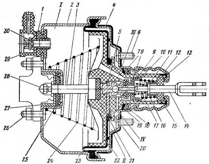
Fig. 48. Brake booster:
1 - tip flange; 2 - body; 3 - easy; 4 - lid; 5 - piston; 6 - amplifier mounting bolt; 7 - distance ring; 8, 10, 11 - support cups; 9, 30 - valves; 12 - protective cover; 13 - cover clip; 14 - pusher; 15 - air filter; 16, 17, 24 - springs; 18 - seal; 19 - retaining ring; 20 - thrust plate; 21 - buffer; 22 - valve body; 23 - diaphragm; 25 - rod seal; 26 - master brake cylinder mounting bolt; 27 - seal collar, 28 - adjusting bolt; 29 - tip; I - vacuum cavity; II - atmospheric cavity; III, IV - connecting channels.
Rubber diaphragm 23 installed between housing 2 and cover 4 divides the vacuum booster into two cavities: vacuum I and atmospheric II. The vacuum cavity is connected to the engine inlet pipe by a hose, in the tip 29 of which valve 30 is located. When the engine is running and the brake pedal is released, the pressure in the vacuum and atmospheric cavities of the booster is the same, since the vacuum from the engine inlet pipe through the hose and tip 29 is transmitted to cavity I and from it to cavity II through channel III, the gap between valve 9, its seat on housing 22 and through channel IV. When braking, pusher 14 moves piston 5 inside housing 2 of the booster, and the movable part of valve 9 is pressed by spring 17 against the seat on housing 22 and disconnects vacuum I and atmospheric II cavities. With further movement of the pusher 14, the piston 5 moves away from the valve 9, and air enters the cavity II through the resulting gap, channel IV and air filter 15. In this case, a vacuum is maintained in cavity I, and atmospheric pressure is established in cavity II. The difference in pressure in the cavities of the booster creates an additional force, which, together with the force of the driver pressing the brake pedal, moves the valve housing 22 with the diaphragm 23. In this case, the rod 3 moves through the buffer 21, which acts on the pistons of the main brake cylinder. When the brake pedal is no longer pressed and it stops in the braked position, the housing 22 together with the valve 9 pressed against it, under the action of the pressure difference in cavities I and II, will move until the valve 9 rests against the end of the stopped piston 5. In this case, the air supply to cavity II will stop, and the housing 22 will take a certain position. If the brake pedal is released in this position, piston 5 will move valve 9 away from body 22, the pressure in cavity II will decrease and, under the action of spring 24, body 22 will move until it comes into contact with valve 9.
During emergency braking, when a large force is applied to the brake pedal, the gap between piston 5 and valve 9 is maintained, and air continues to flow into cavity II of the booster. After braking has ceased, when the brake pedal is released, pusher 14 with piston 5 will return to the initial position under the action of return spring 24. In this case, piston 5 presses valve 9 away from housing 22, some of the air from cavity II will flow into cavity I, and the pressure in the cavities of the booster will equalize. In this case, housing 22 with diaphragm 23 and rod 3 will move to cover 4 of the booster under the action of spring 24 and take the initial position.
Master brake cylinder (Fig. 49) is dual-chamber and simultaneously operates the front and rear brake circuits. It is attached to the brake booster.
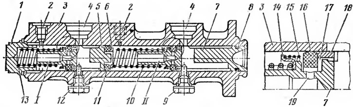
Fig. 49. Master brake cylinder:
1 - cork; 2, 4, 19 - connecting holes; 3 - body; 5 - rear brake drive piston; 6 - washer; 7 - front brake actuator piston; 8, 16 - sealing rings; 9, 12 - piston limit screws; 10, 13, 15 - springs; 11 - cuff; 14 - plate; 17 - gaps; 18 - spacer ring; I - rear brake drive chamber. II - front brake drive chamber.
In the body of the cylinder 3 there are pistons 5 and 7, which activate different brake circuits and differ slightly from each other in their design. The piston 7 is supported by the rod of the vacuum brake booster. The pistons form two chambers I and II in the cylinder, which are connected through openings 2 by pipelines to the wheel brake cylinders of the rear and front brake mechanisms. Through openings 4, the main brake cylinder is connected by pipelines to the brake reservoir. When the brake pedal is released, the return spring 13 moves the piston 5 to the extreme right (initial) position. In this case, the piston rests against the limiter 12, and the piston 7, under the action of the spring 10, rests against the limiter 9. Chambers I and II are separated from each other by the cuff 11, put on the piston 5.
Rubber sealing rings 16 and spacer rings 18 are inserted into the piston ring grooves. In the initial position, spring 15 presses the sealing ring against the spacer ring, as a result of which gaps 17 are formed between the sealing ring, spacer ring and piston. Through these gaps and openings 19, chambers I and II communicate with the brake reservoir, as a result of which the brake fluid in the front and rear brake drive circuits does not experience excess pressure.
When braking, piston 7 moves, annular gap 17 is eliminated, and the piston flange is pressed against sealing ring 16. After this, the fluid from the main brake cylinder is forced out into the wheel brake cylinders, and the fluid pressure required for braking is created in the front brake drive circuit. Piston 5 moves simultaneously with piston 7, increasing the fluid pressure in the rear brake drive circuit. The fluid pressure that occurs in chamber II is transmitted through piston 5 to the fluid in chamber I. Therefore, if the front and rear brake drive circuits are in good condition, the fluid pressure in both circuits is the same.
If the front brake drive circuit is damaged and fluid leaks out of it during braking, piston 7 rests against piston 5. As a result, fluid pressure will be created in chamber I, which will activate the rear brake mechanisms. If fluid leaks out of the rear brake drive circuit during braking, piston 5 rests against plug 1 of the brake cylinder, as a result of which fluid pressure is created in chamber II, which activates the front brake mechanisms.
Rear wheel brake cylinder is mounted on the brake shield of the rear brake mechanism. In the cylinder body there are two pistons, between which an expansion spring with support cups is installed. Stops are pressed into the pistons, into the grooves of which the upper ends of the brake shoes enter. In the cylinder, the pistons are sealed with cuffs. The cylinder is protected from contamination by rubber covers. There are two holes in the cylinder body. A pipe fitting is screwed into the lower hole, supplying brake fluid to the cylinder, and a bypass valve is screwed into the upper hole, designed to remove air from the brake drive.
Pressure regulator (Fig. 50) sets the fluid pressure in the rear brake drive depending on the position of the car body relative to the rear axle. The regulator is included in the rear brake drive circuit and functions as a valve that automatically interrupts the fluid supply to the rear brake mechanisms. As a result, skidding of the rear wheels is eliminated and the vehicle's driving safety is increased.
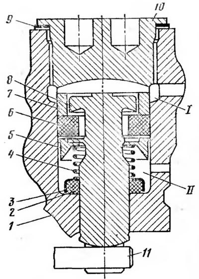
Fig. 50. Pressure regulator:
1 - body; 2 - sealing ring; 3 - clip; 4 - spring; 5 - plate; 6 - rubber seal; 7 - spacer sleeve; 8 - piston; 9 - gasket; 10 - cork; 11 - regulator drive torsion; I, II - regulator cavities.
The housing 1 of the pressure regulator is rigidly fixed to the car body. In the housing of the regulator there is a piston 5, the rod of which rests on the torsion bar 11 of the drive, connected to the rear axle of the car. In the housing there is a bushing 7, between which and the cylindrical head of the piston an annular gap is formed. The rubber seal 6 of the piston head is pressed against the bushing 7. The spring 4, put on the piston rod, rests with one end on the plate 5, and with the other - in the sealing rubber ring 2. Inside the housing of the regulator there are two cavities. Cavity II is connected by a pipeline to the main brake cylinder, and cavity I - with the wheel brake cylinders of the rear brake mechanisms.
The pressure regulator does not work if the vehicle is not braking. In this case, piston 8, under the action of torsion 11 and spring 4, rests against plug 10 of the regulator. Cavities I and II communicate with each other through gaps between the piston, bushing 7 and seal 6.
The force acting on the piston rod from the torsion bar 11 depends on the relative position of the car body and the rear axle. It increases as the body approaches the axle and decreases as it moves away from the rear axle.
During braking, the fluid from the master brake cylinder enters the wheel brake cylinders of the front and rear brakes. Moreover, it enters the brake cylinders of the rear brakes through the pressure regulator. In the regulator body, the brake fluid passes through cavity II, the gaps between the piston, seal 6, bushing 7 and through cavity I. At the beginning of braking, when the pressure on the fluid is small, the fluid freely passes through the regulator, activating the rear brake mechanisms. As the fluid pressure increases, when the brakes are applied, the rear of the car body rises, and the force acting on the piston rod from the torsion bar 11 decreases. Due to the difference in pressure on the piston from above and below, it drops until it stops in seal 6. In this case, cavities I and II will be separated from each other, and the supply of brake fluid to the rear brakes will stop. Moreover, each position of the car body relative to the rear axle will correspond to a certain maximum fluid pressure in the rear brake mechanisms.
Therefore, each value of the load on the rear wheels of the car during braking corresponds to a certain braking torque. This is necessary to reduce the likelihood of skidding of the rear wheels during braking of the car.
At the end of braking, when the rear part of the car body is lowered, the force acting on the piston rod from the torsion bar 11 will increase. The pressure regulator piston will take its initial position, and through the resulting gaps, cavities I and II will connect with each other, and the wheel brake cylinders of the rear brakes - with the main brake cylinder.
Parking brake system
The parking brake system acts on the rear wheels of the car and is driven by a lever with the driver's hand.
The parking brake system includes the rear brake mechanisms and mechanical drive.
The mechanical drive (Fig. 51) includes: hand lever 3, front cable 2, guide 9, rear cable 14, expansion levers 13 and spacer bars 12.

Fig. 51. Mechanical drive of the parking brake system:
1 - case; 2 - front cable; 3 - hand lever; 4 - button; 5 - spring; 6 - traction; 7 - bracket; 8 - lever; 9 - rear cable guide; 10 - spacer sleeve; 11 - release spring; 12 - spacer bar; 13 - release lever; 14 - rear cable.
Lever 3 is pivotally fixed on bracket 7, which is mounted on the floor of the vehicle body. When the lever is moved upward, the force from it is transmitted through lever 8, front cable 2, guide 9 and rear cable 14 to expansion levers 13 and spacer bars 12 and from them to the brake shoes of the rear brake mechanisms. Lever 3 is fixed in a given position by a latch, which is constantly pressed against the toothed sector by spring 5 through rod 6. The latch is released by pressing button 4. Spring 11 ensures the return of the front and rear cables to their original position when lever 3 of the parking brake system is released.