
The steering wheel in the car is located on the left in the direction of travel, which provides better visibility when driving towards oncoming traffic. Injury safety is ensured by the design of the intermediate steering shaft and the special fastening of the steering shaft to the car body.
Steering (pic. 42) consists of a steering mechanism and a steering gear.
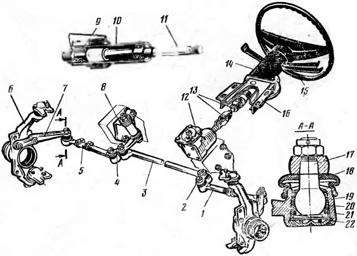
Pic. 42. Steering:
1 - lateral thrust; 2 - steering arm; 3 - medium thrust; 4 - pendulum lever; 5 - adjusting clutch; 6 - rotary fist; 7 - lever of a rotary wader; 8 - pendulum arm bracket; 9 - bearing; 10 - steering shaft bracket pipe; 11 - steering fell; 12 - steering gear housing; 13 - intermediate steering shaft; 14 - steering column; 15 - steering wheel; 16 - bracket; 17 - ball pin; 18 - rubber cover; 19 - thrust tip; 20 - insert; 21 - spring; 22 - plug.
Steering gear increases the effort of the driver and transfers it to the steering gear.
The car uses a worm gear.
The steering mechanism includes: a steering wheel 15, a steering shaft 11, an intermediate shaft 13 and a steering pair (worm and roller).
Steering wheel two-spoke, plastic, with a steel frame. It is fixed on the splines of the upper end of the steering shaft 11, which is installed in the tube 10 of the bracket 16 in two ball bearings 9. The steering shaft with the steering column 14 is attached to the car body using the bracket 16.
The bracket is fastened to the body in such a way that in case of accidents, the steering shaft 11 with the steering wheel moves slightly towards the driver, which ensures his safety. The lower end of the steering shaft is connected through splines to the intermediate shaft 13, which is a cardan shaft with two hinges. The intermediate shaft is also connected through the splines to the shaft 12 (pic. 43) worm 11. The worm is installed in the crankcase 4 in two ball bearings 14, the tightening of which is regulated by means of gaskets 15 installed under the cover 16. The worm is engaged with the roller 6, which is installed in the groove of the shaft head 5 of the steering arm on the axle 17 on needle bearings 18. The steering shaft is installed in the crankcase 4 in bronze bushings 3. The engagement of the worm and the roller is adjusted using the adjusting screw 7, the head of which enters the groove of the shaft 5 of the steering arm. The adjusting screw is screwed into the cover 10 and locked with a nut 8. A steering arm 1 is installed on the splined end of the shaft 5.
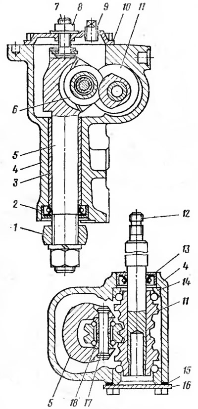
Pic. 43. Steering gear:
1 - steering arm; 2, 13 - glands; 3 - bushing; 4 - crankcase; 5 - steering arm shaft; 6 - roller; 7 - adjusting screw; 8 - nut; 9 - filler plug; 10 - cover; 11 - worm; 12 - worm shaft; 14 - bearing; 15 - shims; 16 - bottom cover; 17 - roller axis; 18 - needle bearing.
Steering gear transmits power from the steering gear to the steered wheels. The steering drive ensures the correct rotation of the steered wheels of the vehicle.
Steering gear (see fig. 42) includes: steering arm 2, pendulum arm 4, lateral 1 and middle 3 thrusts with hinges and levers 7 steering knuckles. The car uses a steering gear with a split steering linkage. Steering trapezoid provides rotation of the steered wheels of the car at different angles (the inner wheel at a greater angle than the outer). It is located behind the axle of the front wheels. The steering trapezoid consists of three transverse rods and levers 7, pivotally connected to each other. The average thrust 3 of the steering trapezoid is made solid. At one end it is connected to the steering arm 2, and at the other end to the pendulum arm 4, which is fixedly fixed on the axis installed in two plastic bushings in the bracket 10, fixed on the car body. The lateral thrust 1 consists of two tips interconnected by an adjusting sleeve 5 fixed on the tips with clamps. This allows you to change the length of the side rods of the steering trapezoid when adjusting the toe of the front steered wheels of the car. The connection of the middle link and side links of the steering trapezoid with a bipod and a pendulum lever, as well as side links with levers 7 of the steering knuckles, is made using ball joints, which provide the possibility of relative movement of the parts of the steering gear in horizontal and vertical planes with simultaneous reliable transfer of forces between them. Ball joints are located in the tips of 19 steering rods. Finger 17 with a spherical head rests on a conical plastic insert 20, which is pressed by a spring 21, which eliminates the gap in the hinge when worn. The ball joint is closed at one end with a plug, and at the other end it is protected by a rubber boot. The hinge pin with its conical part is rigidly attached to the part of the steering gear, to which the steering rod is attached.
Stabilization of steered wheels. The forces acting on the car tend to deflect the steered wheels from the position corresponding to rectilinear motion. To prevent the wheels from turning under the influence of disturbing forces (jolts from driving over bumps in the road, gusts of wind, etc.), the steered wheels must have adequate stabilization. The better it is, the better driving, higher traffic safety, less wear on tires and steering.
On a car, the stabilization of the steered wheels is ensured by the inclinations of their axis of rotation in the transverse and longitudinal planes and the elastic properties of the pneumatic tire.
Cross tilt of the axis of rotation (pic. 44, a), characterized by the angle β, when turning the wheel causes the front of the car to rise to a certain height h. In this case, the mass of the front of the car tends to return the wheel to the position corresponding to the rectilinear movement.
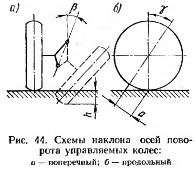
Pitch (pic. 44b), determined by the angle γ, creates a shoulder a, on which the reactions that occur when the wheel turns between the tire and the road at the points of their contact act. These reactions help return the wheel to neutral.
At the car «Niva» VAZ-2121 inclinations of the axis of rotation of the steered wheels are: transverse β = 3°30'±30', longitudinal γ = 6°10'±30'. The transverse inclination of the axis of rotation on the car is adjusted using shims 39 (see fig. 37), installed between the axle 38 of the upper arms and the bracket 2 of the front suspension cross member. The longitudinal inclination of the axis of rotation is regulated by washers 44 (see fig. 37), which are installed on the axis 46 of the lower arm 1 of the front suspension.