
Car suspension (pic. 36) consists of three devices: guide 1, elastic 2 and damping 3.
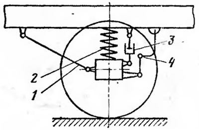
Pic. 36. Schematic diagram of the car suspension:
1, 2, 3 - guiding, elastic and damping devices; 4 - anti-roll bar.
Guide device suspension determines the nature of the movement of the wheel relative to the body and the road. The guide device transmits longitudinal and transverse forces and their moments between the wheel and the car body.
elastic device suspension softens shocks and shocks transmitted from the wheel to the car body when hitting road bumps. The elastic device improves the smoothness of the car, that is, it creates the possibility of movement without discomfort and fatigue for people and damage to the goods being transported.
Extinguishing device The suspension reduces vibrations of the body and wheels of the car that occur when driving over uneven roads. The quenching device converts the mechanical energy of oscillations into thermal energy with its subsequent dissipation into the environment.
In the front suspension of the car, in addition to the elastic, guiding and damping device, there is another additional device - an anti-roll bar. The stabilizer reduces lateral roll and lateral angular vibrations of the car body.
Front suspension
The front suspension of the car is independent, lever-spring, with hydraulic shock absorbers and anti-roll bar.
The front wheels of the car are suspended independently of one another, do not have a direct connection between them, move in a transverse plane, and the movement of one wheel does not cause the movement of the other wheel.
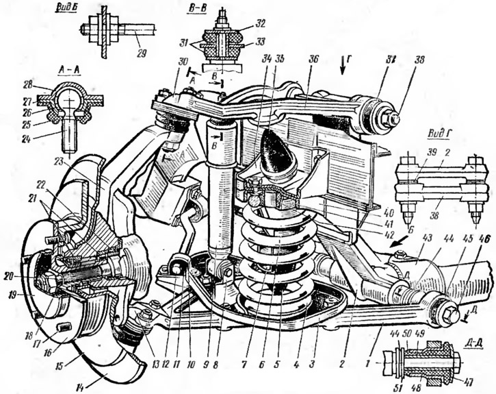
Pic. 37. Front suspension:
1 - lower arm; 2 - cross member bracket; 3 - lower support cup of the spring; 4 - spring; 5 - compression buffer; 6 - compression buffer support; 7 - emphasis; 8 - lower shock absorber bracket; 9 - shock absorber 10 - stabilizer support clip; 11 - rubber stabilizer support; 12 - rod stabilized to the congestion; 13 - lower ball joint; 14 - brake shield; 15 - brake disc; 16 - wheel hub; 17 - stud for fastening the wheel and brake disc; 18 - conical bushing; 19 - decorative cap; 20 - shank of the outer hinge of the wheel drive; 21 - wheel hub bearings; 22 - stuffing box; 23 - rotary fist; 24 - ball joint pin; 25 - protective cover; 26 - bearing; 27 - clip; 28 - body; 29 - stretching; 30 - upper ball joint; 31 - rubber shock absorber cushion; 32 - pillow cup; 33 - upper shock absorber bracket; 34 - recoil buffer bracket; 35 - recoil buffer; 36 - upper arm; 37 - rubber-metal hinge of the upper arm; 38 - axis of the upper arm: 39, 44 - shims: 40 - upper spring support; 41 - upper support cup of the spring; 42 - spring gasket; 43 - cross member of the front suspension; 45 - rubber-metal hinge of the lower arm; 46 - the axis of the lower arm; 47, 51 - thrust washers; 48 - outer sleeve; 49 - inner sleeve: 50 - rubber sleeve.
Front suspension guide (pic. 37) are levers 1 and 36, the elastic device is twisted coil springs 4, the damping device is telescopic hydraulic shock absorbers 9, and the anti-roll bar is an elastic rod 12. The front suspension is mounted on a cross member 43 attached to the car body. Stretch marks 29 are installed between the cross member and the body, which, when the vehicle is moving, perceive the longitudinal forces and their moments transmitted from the front wheels to the cross member. Upper 36 and lower 1 suspension arms are mounted across the vehicle and have longitudinal rolling axes. The axis 46 of the lower arm is attached to the tubular cross member 43, and the axle 38 of the upper arm is attached to the bracket 2 of the cross member. The inner ends of the upper and lower arms are connected to the axles by rubber-metal hinges. The upper 37 and lower 45 rubber-metal hinges have the same device and differ only in their dimensions. The use of rubber-metal hinges ensures silent operation of the suspension and eliminates the need for lubrication of the hinges. The outer ends of the upper and lower suspension arms are connected to the steering knuckle 23 by ball joints 30 and 13. The ball joints are non-separable, have the same design, are interchangeable and do not require lubrication during operation. Suspension spring 4 is installed between the lower support cup 3 attached to the lower arm and the upper support cup 41 connected to the support 40, which is connected to the suspension cross member. Between the ends of the spring and the support cups, vibration-noise insulating pads 42 are installed. The upper end of the shock absorber is attached to the bracket 33 through rubber pads 31. The upward movement of the wheel is limited by a 5% compression buffer which is fixed on a support 6 installed inside the suspension spring. Under static load, the buffer 5 touches the lower support cup 3 of the spring, which ensures its constant operation. The stop 7 limits the compression of the buffer 5. The downward movement of the wheel is limited by the recoil buffer 35, which is installed in the bracket 34, connected to the cross member 43 and the support 40. When the wheel moves down, the buffer 35 rests against a special support pad of the upper arm 36. The anti-roll bar is an elastic torsion type device installed across the car. The stabilizer rod 12 has a U-shape, round section. It is made of spring steel. The middle part of the stabilizer rod and its ends are attached in rubber supports 11 by clips 10, respectively, to the car body and the brackets of the support cups 3 of the lower suspension arms. With side rolls and transverse angular vibrations of the body, the ends of the stabilizer bar move in different directions: one end lowers and the other rises. As a result, the middle part of the stabilizer bar is twisted, thereby reducing the roll and lateral swing of the car body. By creating resistance to roll and lateral vibrations of the body, the stabilizer at the same time does not interfere with its vertical and longitudinal angular vibrations.
With such oscillations, the stabilizer rod rotates freely in its supports.
Rear suspension
Rear suspension dependent, spring, with hydraulic shock absorbers. The rear wheels of the car are interconnected by a beam of the rear axle, as a result of which the movement of one of the wheels in the transverse plane is transmitted to the other wheel. rear suspension guide (pic. 38) are longitudinal 3, 17 and transverse 24 rods, the elastic device is twisted coil springs 9, and the damping device is telescopic hydraulic shock absorbers 25.
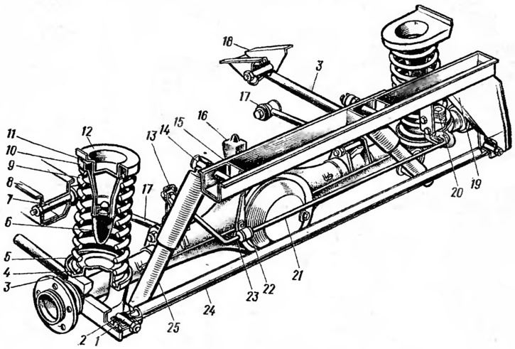
Pic. 38. Rear suspension:
1 - spacer sleeve; 2 - rubber bushing; 3, 17 - lower and upper longitudinal bars; 4, 11 - spring gaskets; 5 - lower support cup of the spring; 6 - compression buffer; 7 - finger of the upper longitudinal rod; 8 - bracket for the upper longitudinal rod; 9 - spring; 10 - spring cup; 12 - upper support cup of the spring; 13 - thrust lever of the brake pressure regulator; 14 - shock absorber pin; 15 - body cross member; 16 - additional buffer; 18 - bracket for the lower longitudinal rod; 19 - cross bar bracket; 20 - brake pressure regulator; 20 - regulator lever; 22 - clip; 23 - sleeve; 24 - transverse rod; 25 - shock absorber.
The rear axle is connected to the car body with the help of four longitudinal 3 and 17 and one transverse 24 rods. Rods 3 and 24 are steel, tubular, and rods 17 are solid. The ends of all rods, except for the front ends of the upper longitudinal rods 17, are fixed in brackets on the car body and the rear axle beam. The front ends of the rods 17 are cantilevered on the fingers 7. Rubber-metal hinges are used to fasten all the rods. Rubber-to-metal pivots ensure quiet operation of the rear suspension and do not require lubrication. Suspension springs 9 are installed between the lower support cups 5 welded to the rear axle beam and the upper support cups 12 connected to the car body. Vibration and noise insulating pads 4 and 11 are installed between the ends of the springs and the support cups. The shock absorbers 25 are mounted cantilevered on the pins 14 to the car body by their upper ends, and to the rear axle beam by their lower ends. Rubber-metal hinges are used for fastening shock absorbers.
The upward movement of the wheels is limited by compression buffers 6, which are fixed on supports installed inside the suspension springs. An additional buffer 16 limits the travel of the front part of the rear axle housing when the wheels move upwards. The downward travel of the wheels is limited by shock absorbers, which reduce the movement of the rear axle when it moves down.
Shock absorbers
Shock absorbers are designed to dampen vibrations of the body and wheels of the car. Hydraulic shock absorbers as a result of the resistance they create (fluid friction) convert the mechanical energy of vibrations of the body and wheels into thermal energy, which is dissipated into the environment. The front and rear suspensions of the car are equipped with double-acting hydraulic shock absorbers of the telescopic type, which dampen vibrations of the body and wheels of the car both during compression and rebound strokes.
The front and rear shock absorbers have the same device and differ only in length and mounting method.
shock absorber (pic. 39) consists of three main units: a cylinder 12 with a bottom 2, a piston 10 with a rod 13 and a guide sleeve 21 with seals. The shock absorber piston has two rows of through holes located along the circumference. The holes of the outer row are closed from above by a bypass valve 24, which is under the influence of a weak lamellar spring 23, and the holes of the inner row are closed from below by a recoil valve 29 with a strong spring 9. At the bottom of the shock absorber cylinder there is a compression valve, the clip 6 and the plate 7 of which have a series of through holes. Cylinder 12 is filled with shock absorber fluid, which is prevented from flowing out by stuffing box 18 pressed by nut 15, which is screwed into reservoir 11. The shock absorber cavity enclosed between cylinder 12 and reservoir 11 is a chamber that serves to compensate for changes in the volume of fluid in the cylinder on both sides of the piston, arising from the movement of the rod 13.
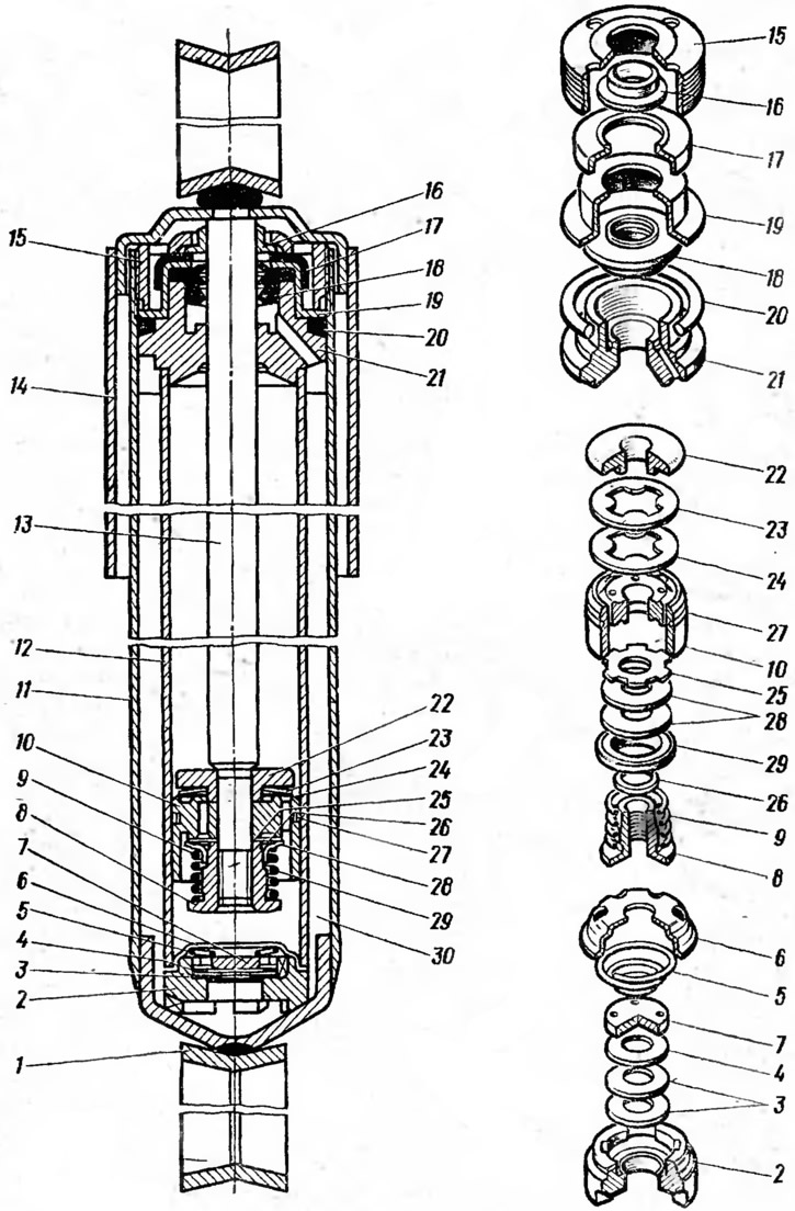
Pic. 39. Shock absorber:
1 - eye; 2 - bottom; 3 - compression valve disks; 4 - throttle disk of the compression valve; 5 - compression valve spring, 6 - compression valve clip; 7 - compression valve plate; 8 - recoil valve nut; 9 - recoil valve spring 10 - piston; 11 - tank; 12 - cylinder; 13 - stock; 14 - casing; 15 - tank nut; 16 - protective ring; 17 - protective ring gasket; 18 - stem gland; 19 - stuffing box holder; 20 - sealing ring; 21 - rod guide sleeve; 22 - restrictive plate; 23 - bypass valve spring; 24 - bypass valve plate: 25 - recoil valve throttle disc; 26 - washer; 27 - piston ring; 28 - recoil valve discs; 29 - recoil valve plate; 30 - compensation chamber.
During the compression stroke, the piston 10 moves down and the rod 13 enters the cylinder 12. The pressure exerted by the piston on the liquid displaces it in two directions: into the space above the piston and into the compensation chamber 30. Having passed through the outer row of holes in the piston, the liquid opens the bypass valve 24 and enters from under the piston into the space above it. Part of the liquid, the volume of which is equal to the volume of the rod introduced into the cylinder, enters the compensation chamber through the compression valve, increasing the pressure of the air located there.
During the recoil stroke, the piston moves up, and the rod exits the shock absorber cylinder. Bypass valve 24 closes and the fluid pressure above the piston increases. The liquid through the inner row of holes in the piston and the recoil valve 29 enters the space under the piston. At the same time, under the action of air pressure, part of the fluid from the compensation chamber also enters the shock absorber cylinder.
With a smooth return, the valve 29 is closed, and the liquid passes through the grooves of its throttle disc 25. With a sharp return, the piston speed increases, under the influence of increased pressure, the return valve 29 opens, and the liquid passes through it.
The rebound valve relieves the shock absorber and suspension from the heavy loads that occur during high-speed vibrations when the vehicle is moving on rough roads. The valve also limits the increase in shock absorber resistance in the event of an increase in fluid viscosity at low temperatures.
The resistance created by the shock absorber during the compression stroke is several times less than during the rebound stroke: 5 times for the front shock absorber and 4 times for the rear shock absorber. This is necessary so that shocks and shocks from road bumps are minimally transmitted to the car body.