
Wheel (pic. 40) consists of a pneumatic tire 7, a rim 2, a disc 3 and a hub 4. The pneumatic tire smooths out road bumps and, together with the suspension, softens and absorbs shocks and shocks from road bumps, ensures a smooth ride of the car. The rim and disk are designed to install a pneumatic tire and connect it to the wheel hub. The hub provides the installation of the wheel on the bridge and allows the wheel to rotate.
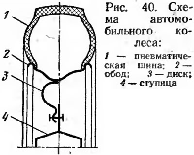
The car has disc wheels. Tires are chambered, have toroidal (round) profile and diagonal arrangement of cord threads. Tire designation 175-16 / 6.95-16. The internal air pressure in the tires of the front wheels is 1.8 kgf / cm2 (0.18 MPa), and in the tires of the rear wheels 1.7 kgf / cm2 (0.17 MPa). Rims and disks of a wheel steel, stamped. The rims have a special profile. The discs have a curved profile to increase their rigidity. They are welded to the wheel rims. The discs have two rows of holes arranged around the circumference. Some holes serve to fasten the wheel to the hub, while others reduce the mass of the wheel, facilitate assembly and disassembly work and improve the cooling of the brakes and tires.
The hub of the front wheels is flanged. It is made from alloy steel. Hub 16 (see fig. 37) mounted in the steering knuckle 23 on two tapered roller bearings 21. The outer rings of the bearings are pressed into the steering knuckle, and the inner ones are mounted on the hub shank, which has internal splines and is connected to the shank 20 of the outer hinge housing of the front wheel drive of the car. The taper bushing 18 ensures the correct installation of the shank 20 relative to the wheel hub. The position of the bearings on the hub is fixed with a nut. Hub bearings are lubricated during assembly.
To protect the bearings from dust, dirt and moisture, as well as to retain lubricant in the steering knuckle, oil seals 22 and protective rings are installed, and on the outside there is a stamped decorative cap 19. Using spherical nuts and studs 17, a wheel and a brake disc 15 are attached to the hub. mechanism. The rear wheel hub is missing. Her, replaces axle shaft flange 9 (see fig. 33), which is the rotating seat of the wheehp the help of spherical nuts and studs, the wheel and brake drum 2 are attached to the axle shaft flange.
To create the least resistance to movement, reduce tire wear and reduce fuel consumption, the steered wheels must roll in vertical planes parallel to the longitudinal axis of the vehicle. For this purpose, the steered wheels are installed on the vehicle with camber in the vertical plane and with convergence in the horizontal plane.
Camber angle of steered wheels is the angle α (pic. 41, a), enclosed between the plane of the wheel and a vertical plane parallel to the longitudinal axis of the vehicle. The camber angle is necessary in order to ensure that the wheels are perpendicular to the road surface when the axle parts are deformed under the influence of the mass of the front of the car.
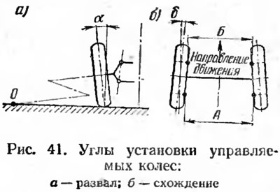
In the presence of camber, the wheel tends to roll from the longitudinal axis of the car along an arc around the point O of the intersection of the continuation of the wheel axis with the road plane. To eliminate this phenomenon, the wheels are installed with convergence, that is, not parallel, but at some angle to the longitudinal axis of the car.
Angle of convergence of the steered wheels is the angle δ (pic. 41.6), determined by the difference between the distances A and B between the wheels, which are measured at the back and front along the edges of the rims at the height of the wheel axle.
At the car «Niva» VAZ-2121, the installation angles of the steered wheels are: camber α = 0°30'±20', toe δ = A - B - 3±1 mm.
During the operation of the car, the camber angles of the steered wheels change due to wear of the front suspension joints, front wheel bearings and deformation of the front suspension cross member. The toe angles of the wheels change due to the wear of the articulated joints of the steering trapezium and the deformation of its levers.
The camber of the steered wheels on the car is adjusted using shims 39 (see fig. 37), which are installed between the axis 38 of the upper arms and the bracket 2 of the front cross member 'suspension. The convergence of the steered wheels is regulated by changing the length of the side rods of the steering trapezoid using adjusting clutches.