
Removing
Disconnect wires from the storage battery and take out facing of a cover of a signal. Loosen the steering wheel nut, remove the steering wheel and then both halves of the steering shaft cover.
Note. If it is necessary to remove only the steering gear housing, unscrew the bolt securing the lower cardan joint of the intermediate shaft to the worm shaft and the bolts securing the crankcase to the body side member.
Remove the instrument panel and disconnect the three-lever switch connectors from the cable harness connectors.
Disconnect the wires from the ignition switch terminals and, having unscrewed the mounting screws and drowned the lock latch, remove the ignition switch. Loosen the clamp securing the turn signal, headlight and wiper switch housing and remove it.
Turn away a bolt of fastening of a plug of the lower universal joint of an intermediate shaft to a shaft of a worm of the steering mechanism.
Loosen the bracket mounting bolts 6 (pic. 5-3) and remove the steering shaft with bracket.
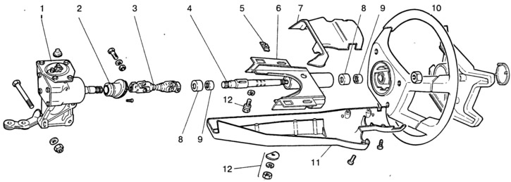
Pic. 5-3. Steering Details:
1 - steering gear housing; 2 - shaft seal; 3 - intermediate shaft; 4 - upper shaft; 5 - fixing plate of the front part of the bracket; 6 - bracket; 7 - upper part of the facing casing; 8 - bearing sleeve; 9 - needle bearing; 10 - steering wheel; 11 - lower part of the facing casing; 12 - fastening details of the steering shaft bracket.
Unscrew the nuts securing the ball pins of the side and middle rods to the bipod, and then press the ball pins out of the holes of the bipod with a puller A.47035.
Remove the steering gear housing by first unscrewing the bolts of its fastening to the body side member. Remove the steering shaft seal from the hole in the body bulkhead.
Installation
Install sealant 2 into the hole in the front end of the body (pic. 5-3), aligning the protrusions of the seal with the groove of the hole in the front end of the body, install the steering gear housing on the side member, without fully tightening the nuts of the crankcase mounting bolts.
Use a special device to orient the crankcase so that the angle a (pic. 5-4) did not exceed 32°, and the gap between the shaft and the brake pedal was not less than 5 mm. Then fully tighten the crankcase bolt nuts.
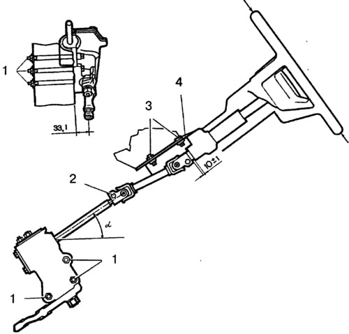
Pic. 5-4. Installation of the steering mechanism on the car:
1 - bolts for fastening the crankcase of the steering mechanism; 2 - coupling bolt for fastening the lower end of the intermediate shaft; 3 - bracket mounting bolts; 4 - steering shaft bracket; 33.1 mm - distance from the center of the bipod hole to the bearing surface of the steering gear case with the bipod in the middle position; 10 + 1 mm - the distance from the universal joint yoke of the intermediate shaft to the end of the bracket.
Set the bipod of the steering mechanism to the middle position, for which align the marks on the crankcase and on the worm shaft (rice. 5-2).
Install the steering wheel temporarily on the shaft so that the spokes are horizontal, and in this position connect the universal joint yoke of the intermediate steering shaft to the worm shaft, paying attention to the fact that the tie bolts pass through the annular groove of the worm. Then attach the steering shaft bracket to the body.
Remove a steering wheel and put on a steering shaft the switch of indexes of turn, light of headlights and screen wipers.
Install the steering wheel on the steering shaft so that the steering wheel spokes are horizontal. Check that the steering wheel rotates smoothly and freely in both directions, then tighten the steering wheel nut and tighten it at three points. Slide the turn signal, headlight and wiper switch housing towards the steering wheel until it stops and tighten the switch mounting clamp.
Connect the wires to the ignition switch terminals and screw the switch to the steering shaft bracket.
Connect the turn signal, headlight, and wiper switch connectors to the vehicle harness connectors.
Mount both halves of the cladding on the shaft and fasten them with screws. Apply a light coat of grease to the surface of the steering wheel lower slip ring and install the horn switch cover trim to the steering wheel.
Install the middle and side left-hand ball pins on the bipod and secure them with nuts.
Adjust the toe of the front wheels and check the force on the steering wheel, which, when turning the wheels on a smooth metal plate, should not exceed 196 N (20 kgf), 245* H (25* kgf) (when measured on the wheel rim).
Note. You can separately assemble the steering shaft with the turn signal, headlight and wiper switch, steering wheel and install this assembly on the car.
To mount the assembly, position the steering wheel spokes horizontally and connect the worm shaft to the lower end of the intermediate steering shaft, making sure that the lock bolts pass through the annular groove of the worm shaft and the steering shaft.
With the bracket bolts not fully tightened, turn the steering wheel to both sides several times, then tighten the bracket bolts.