
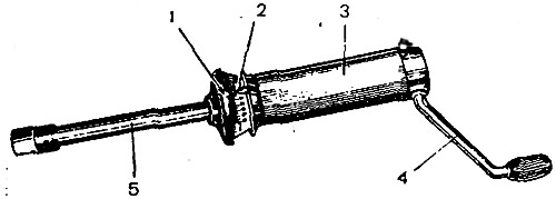
Pic. 3-78. Dynamometer 02.7812.9501: 1 - movable pointer; 2 - torque limit indicator; 3 - body; 4 - handle; 5 - rod with a tip inserted into the adapter sleeve
The torque of resistance to rotation determines the degree of tightening of the bearings. It should be 157-196 Ncm (16-20 kts cm) for new bearings, 39.2-58.8 Ncm (4-6 kgf cm) - for bearings after a run of 30 km or more.
Tighten the flange nut with a torque of 118-255 Nm (12-26 kgf·m) periodically checking with a dynamometer the moment of resistance of the bearings to turning the drive gear.
To check the moment of resistance, put a dynamometer on the adapter sleeve 3 (pic. 3-79), set pointer 2 (pic. 3-78) torque limitation scale endowment corresponding to 196 Ncm (20 kgf cm), and turn knob 4 a few turns clockwise. While turning the drive gear, the movable pointer 1 must not go beyond the pointer 2 and must show at least 157 Ncm (16 kgf cm).
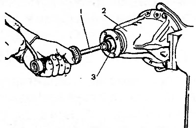
Pic. 3-79. Checking the preload of the pinion bearings: 1 - dynamometer 02.7812.9501; 2 - crankcase; 3 - adapter sleeve
If the torque is less than 157 Ncm (16 kgf cm), and for bearings after 30 km run 39.2 N cm (4 kgf cm), then tighten the pinion flange nut (without exceeding the specified tightening torque) and check again the moment of resistance to turning the drive gear.
If the moment of resistance to rotation is more than 196 Ncm (20 kgf cm), and for run-in bearings 58.8 N cm (6 kgf cm), indicating that the bearing preload is too high, replace the spacer sleeve with a new one, as it has deformed from excessive load to a size that does not allow for correct adjustment. After replacing the spacer sleeve, repeat assembly with appropriate adjustments and checks.
Installing the differential box
Install the pre-assembled differential case into the crankcase along with the bearing outer races.
Install two adjusting nuts 4 (pic. 3-80) so that they are in contact with the bearing rings.
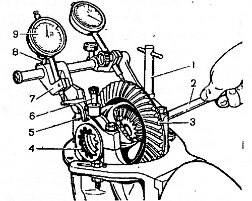
Pic. 3-80. Checking the differential box bearing preload with tool A.95688/R: 1 - fixture screw; 2 - key A.55085; 3 - driven gear; 4 - adjusting nut; 5 - intermediate lever; 6 - fastening screw; 7 - indicator bracket; 8 - bracket mounting screw; 9 - indicator for checking bearing preload
Install the bearing caps and tighten the mounting bolts with a torque wrench.
Preload bearings of the differential box and adjustment of the backlash in the meshing of the final drive gears
These operations are carried out simultaneously using tool A.95688/R and key A.55085.
Attach the tool to the gearbox housing (pic. 3-80) screws 1 and 6, screwing them into the holes for the bolts of the locking plates of the adjusting nuts.
Move bracket 7 along the guide of the fixture until lever 5 touches the outer side surface of the cover and tighten screw 8.
Loosen screws 1 and 3 (pic. 3-81) and install the bracket 4 so that the indicator leg 2 rests on the side surface of the driven gear tooth at the edge of the tooth, then tighten the screws 1 and 3.
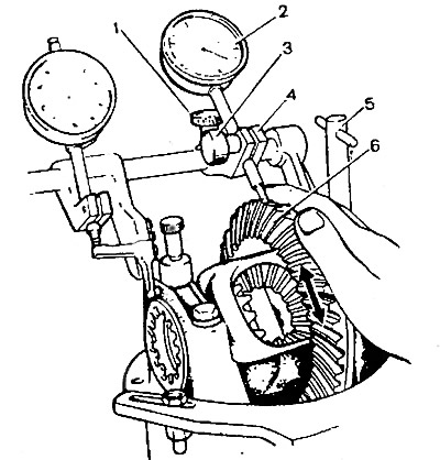
Pic. 3-81. Checking the backlash in the meshing of the final drive gears with tool A.95688/R: 1 - bracket mounting screw; 2 - indicator for checking the side clearance in the meshing of gears; 3 - screw for fastening the indicator rod; 4 - indicator bracket; 5 - fastening screw; 6 - driven gear
By turning the adjusting nuts, pre-adjust the backlash between the teeth of the driving and driven gears within 0.08-0.13 mm. The gap is checked by indicator 2 while rocking gear 6. In this case, the bearings should not have a preload. The adjusting nuts must only be in contact with the bearings, otherwise the correct preload measurement will be impaired.
Tighten the two bearing adjusting nuts sequentially and evenly, this will cause the differential bearing caps to move apart and thus increase the distance «D» (pic. 3-82). This discrepancy is marked by indicator 9 (pic. 3-80), on the leg of which the lever acts 5. The nuts for adjusting the bearings of the differential box are tightened to increase the distance «D» (pic. 3-82) by 0.14-0.18 mm.
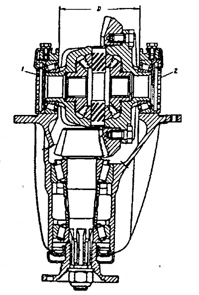
Pic. 3-82. Scheme for checking the preload of differential box bearings: D is the distance between the two differential bearing caps; 1, 2 - adjusting nuts
Having set the exact preload of the bearings of the differential box, finally check the backlash in the meshing of the final drive gears, which should not change.
If the gap in the meshing of the gears is more than 0.08-0.13 mm, then move the driven gear closer to the drive gear or move it away if the gap is smaller. To maintain the set bearing preload, move the driven gear by tightening one of the bearing adjusting nuts and loosening the other by the same angle.
To accurately perform this operation, watch the indicator 9 (pic. 3-80), which shows the previously set bearing preload. After tightening one of the nuts, the indicator reading will change, as the discrepancy will increase «D» (pic. 3-82) caps and bearing preload. Therefore, loosen the other nut until the indicator needle returns to its original position.
After moving the driven gear, according to indicator 2 (pic. 3-81) check backlash If the backlash is out of specification, repeat the adjustment.
Remove tool A.95688/R, fit the locking plates of the adjusting nuts and secure them with bolts and spring washers. Spare parts are supplied with locking plates of two types: with one or two tabs, depending on the position of the nut slot.
The adjustment and repair of the gearbox units is carried out on a stand, where you can also test the gearbox for noise and check the location and shape of the contact patch on the working surfaces of the teeth, as indicated below.