




Contents: Removal and installation of the…↓ Disassembly and assembly of the…↓ Features of the valve mechanism ↓
Engine 21214-10 is a four-stroke, four-cylinder engine with in-line vertical cylinders and overhead camshaft, with a distributed fuel injection system.
Engine 21214-10 is based on engine 21213. They have identical body parts and crank mechanism. Identical suspension of the power unit. Differences in the engine design are associated with the use of a distributed fuel injection system on this engine instead of a carburetor, with the use of hydraulic pusher supports and a hydraulic chain tensioner in the gas distribution mechanism. Therefore, there are features in the assembly and disassembly of the engine, in terms of removing and installing air supply units, the fuel system and the lubrication system.
Removal and installation of the power unit
Before removing the power unit, it is necessary to relieve the pressure in the fuel supply system. To do this, disconnect the electrical fuel pump wiring harness connector from the injection system wiring harness, start the engine, let it run until it stops, and then turn on the starter for 3 seconds to equalize the pressure in the pipelines.
Disconnect the wire from the negative terminal of the battery.
Disconnect fuel supply and drain hoses 7 and 8 (Fig. 9-14) from pipes 1 and 9 on the engine. Close the openings of the hoses and pipes to prevent dirt from getting into them.
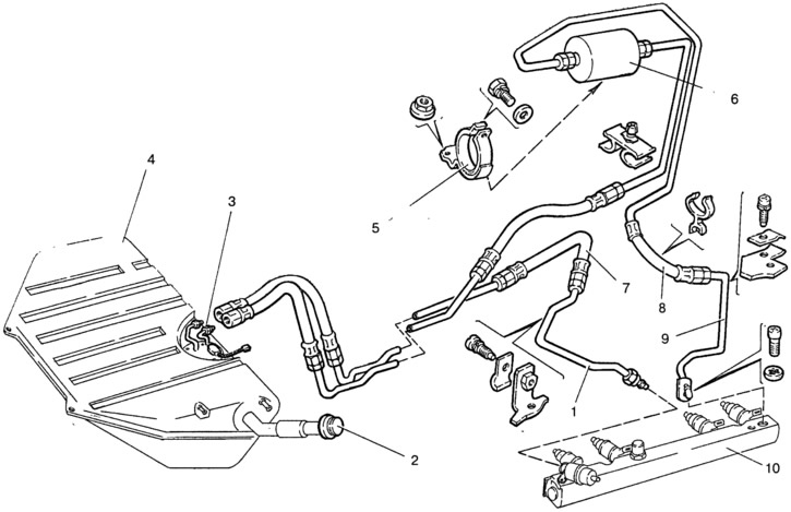
Fig. 9-14. Fuel tank parts and fuel lines:
1 - outlet pipe; 2 - cork; 3 - electric fuel pump; 4 - fuel tank; 5 - fuel filter mounting bracket; 6 - fuel filter; 7 - fuel line drain hose; 8 - fuel supply hose; 9 - fuel supply pipe; 10 - fuel rail.
Disconnect cable 4 (Fig. 9-15) of the accelerator drive from bracket 5 on the throttle pipe, from sector 6 on the receiver and from bracket 3 on the cylinder head cover.
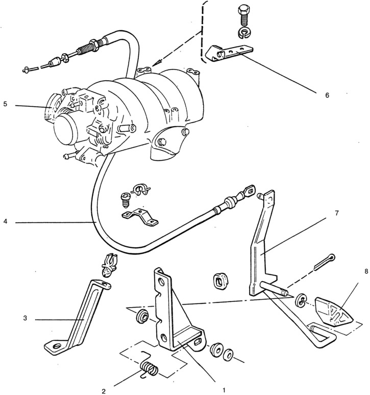
Fig. 9-15. Removing the accelerator drive:
1 - bracket; 2 - return spring; 3 - supporting bracket; 4 - throttle control cable; 5 - cable mounting bracket; 6 - sector with throttle control lever; 7 - throttle control pedal; 8 - pedal cover.
Loosen the two clamps and remove hose 6 (Fig. 9-16) of the intake pipe, disconnecting the engine crankcase ventilation hose from its branch pipe.
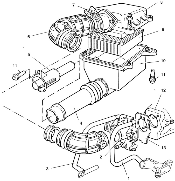
Fig. 9-16. Removing air supply system components and parts:
1 - throttle body heating hose; 2 - throttle pipe; 3 - hose leading from the throttle pipe; 4 - air intake; 5 - air intake tip; 6 - Inlet pipe hose; 7 - mass air flow sensor; 8 - Air filter cover; 9 - filter element; 10 - Air filter housing; 11 - filter support; 12 - receiver; 13 - gasket.
Remove the air filter assembly with the mass air flow sensor 7 by cutting off with a knife three rubber supports 11, with which the filter is attached to the body, and one support that attaches the cold air intake tip to the radiator.
Disconnect the vacuum hoses from the receiver to the fuel pressure regulator and to the brake booster.
Disconnect the purge hose from the throttle body (if the vehicle has a gasoline vapor recovery system).
Disconnect the wires from the throttle body, from the ignition module, from the injector wiring harness, from all sensors located on the powertrain, and from the reverse light switch on the transmission.
Further removal of the power unit is carried out in the usual manner, as described in section 2.
The power unit is installed in the reverse order of removal. The rubber air filter mounting supports are disposable. Therefore, when installing the air filter, install new supports.
After installing the power unit, adjust the accelerator drive. When the accelerator pedal 7 (Fig. 9-15) is fully released, the throttle valve should be fully closed. The drive cable should be taut. The cable deflection from hand force should be no more than 10 mm. If necessary, adjust the drive cable tension with the adjusting nuts of the cable end.
When the accelerator pedal is fully depressed to the stop, the throttle valve should be fully open, the throttle valve bracket 5 should not have any additional travel.
Check the operation of the injection system as described in the Multi-Point Fuel Injection System Repair Manual.
Disassembly and assembly of the engine
The main differences in engine disassembly and assembly are related to the different design of the air supply system.
After installing the engine on the stand and draining the oil from the crankcase, disassemble the engine in the following order.
Disconnect coolant supply and discharge hoses 1 and 3 from throttle pipe 2 (Fig. 9-16), as well as the idle crankcase ventilation hose. Remove the throttle pipe with gasket 13 by unscrewing the nuts securing it to receiver 12.
Remove fuel supply and drain pipes 9 and 1 (Fig. 9-14), disconnecting them from the injector rail 10, the fuel pressure regulator and from the bracket on the receiver. Remove vacuum hose 6 (Fig. 9-17), disconnecting it from the pipes on the receiver 8 and the fuel pressure regulator 5.
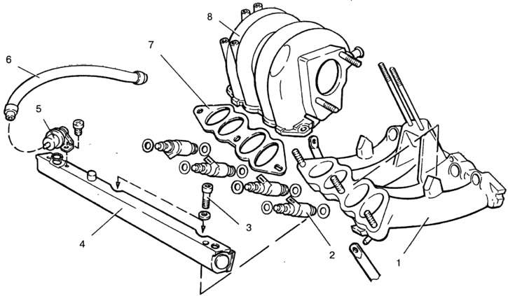
Fig. 9-17. Removing the power supply system components:
1 - inlet pipe; 2 - nozzle; 3 - bolt; 4 - injector ramp; 5 - pressure regulator; 6 - vacuum hose; 7 - gasket; 8 - receiver.
Remove the receiver with gasket 7 by unscrewing the five nuts securing it to the intake pipe 1.
Disconnect the wiring harness from the injectors, remove the injector rail 4 with the pressure regulator 5 by unscrewing the two bolts 3 securing it to the intake pipe.
After unscrewing the nuts and bolts, remove the brackets and then the intake pipe with the screen.
From the left side of the engine, remove the ignition module and knock sensor.
Further disassembly of the engine is carried out in the usual manner, as indicated in Section 2 of this Manual.
The engine assembly is performed in the reverse order of disassembly. Before installing the fuel rail, lubricate the injector sealing rings with engine oil.
Features of the valve mechanism
Valves 2 (Fig. 9-18) are actuated by the camshaft cams via levers 3. One end of the lever presses on the valve, and the other rests on the spherical head of the hydraulic support 6. The hydraulic supports automatically eliminate the gap in the valve mechanism, and therefore, when servicing the car, it is not necessary to check and adjust the gap in the valve mechanism.
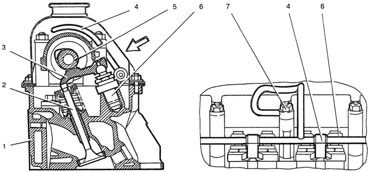
Fig. 9-18. Valve drive mechanism:
1 - cylinder head; 2 - valve; 3 - valve lever; 4 - hydraulic support ramp of the pusher; 5 - camshaft; 6 - hydraulic pusher support; 7 - nut.
Oil from the lubrication system enters the tensioner cavity "E" (Fig. 9-20) through pipe 3 (Fig. 9-19), then through opening "D" and valve unit 2 enters the working cavity "B" and presses on plunger 5. In the tensioner housing 1 there is an opening with a diameter of 1 mm for bleeding air into cavity "E".
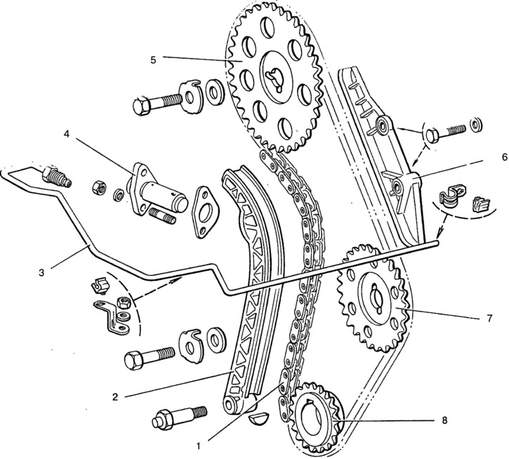
Fig. 9-19. Elements of the chain tensioning mechanism:
1 - chain; 2 - tensioner shoe; 3 - oil supply pipe to the tensioner; 4 - chain tensioner; 5 - camshaft sprocket; 6 - pacifier; 7 - oil pump drive shaft sprocket; 8 - crankshaft sprocket.
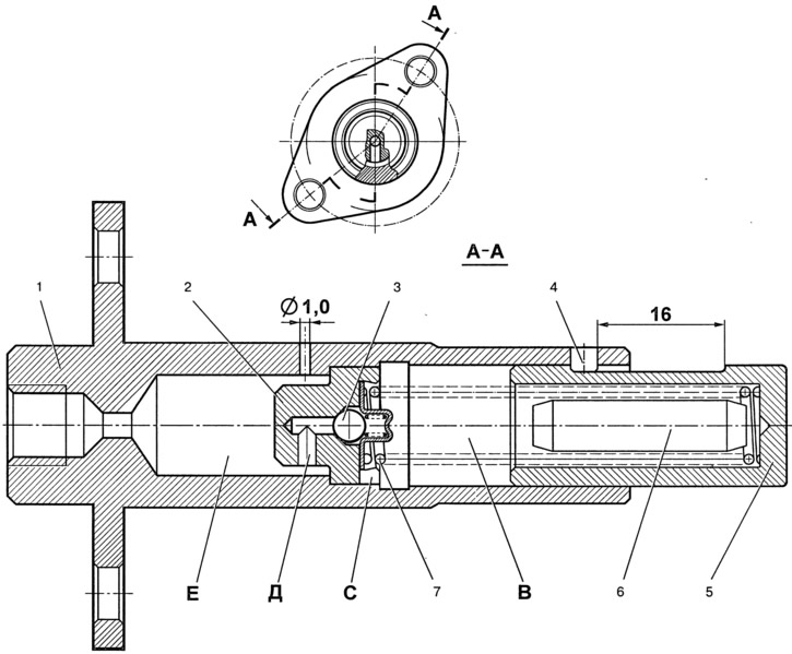
Fig. 9-20. Hydraulic chain tensioner:
1 - tensioner housing; 2 - valve unit; 3 - check valve ball; 4 - limit pin; 5 - tensioner plunger; 6 - volume limiter; 7 - plunger spring; B - working cavity; C - installation groove; D - hole; E - reserve cavity.
The diametrical gap between body 1 and plunger 5 should be 0.018-0.024 mm and is measured as the difference between the maximum measured diameter of plunger 5 and the minimum measured diameter of body 1.
During repair, the tensioner body and plunger form a pair, in which replacement of one part by the other after selection of the gap is not allowed. Plunger 5 must move in body 1 without jamming by a stroke value equal to 16 mm.
When installed on the engine, the tensioner must be free of oil, pin 4 must not protrude from the housing.