




This chapter provides a brief description of the diagnostics of fuel and electrical equipment, the procedure for removing and installing the engine, and also describes the features of repairing engine systems.
The design, repair and diagnostics of all engine systems using special devices and diagnostic cards are described in detail in the PEUGEOT Engine Repair Manual.
The operation of a diesel engine largely depends on the serviceability of the fuel injection system, so this section focuses on the fuel equipment.
If the injection system malfunctions, do not immediately blame the high-pressure pump, but first check:
- fuel tank condition and filling;
- fuel supply and return lines;
- fuel filter;
- serviceability of injectors;
- glow plug condition;
- resistance of the engine stop solenoid valve.
It is also necessary to check the general condition of the engine, since achieving a high ignition temperature of the injected fuel depends on the compression, condition of the valves, and piston rings.
Also check the condition of the air filter, battery, starter, and oil level.
Main faults and troubleshooting methods
1. The engine does not start without emitting smoke:
- check for fuel in the tank;
- set the manual engine stop device to the normal position;
- check the fuel supply pipes, if there is a leak, fix it by tightening the connections or replace the pipes;
- check the engine shut-off solenoid valve for continuity of electrical wiring and fuel supply, as well as its resistance.
If after these checks and troubleshooting the engine does not start, remove the high pressure pump and check it on special equipment.
2. The engine does not start and emits black smoke:
- if the number of revolutions of the crankshaft is less than 150 rpm, check the condition and tightening of the terminals on the battery (battery) and starter, charging the battery, grade and oil level;
- if the crankshaft speed exceeds 150 rpm, start the engine without the air filter, if the smoke has disappeared, replace the filter element, check the correct installation of the air filter housing;
- check the correctness of the injection advance setting, the serviceability of the injectors;
- check valve adjustment, compression in cylinders.
If the smoke remains after all faults have been eliminated, remove and check the pump using special equipment.
3. The engine does not start and emits white smoke (cold engine):
- check the glow plugs;
- check the secondary heating system;
- check the condition of the cylinder head gasket;
- check the injection advance adjustment.
If smoke remains after repair work, remove the pump for inspection.
4. Cold engine starts with difficulty and produces black smoke:
- check the glow plugs;
- check fast idle thermostat;
- check the injection advance adjustment;
- check the condition of the injectors;
- check hydraulic lifters and valve clearances;
- check the compression.
If the smoke remains after the repair, remove and check the pump using special equipment.
5. The engine starts and stalls:
- check idle speed adjustment;
- check the oil type and level;
- check the ventilation system;
- check the fuel supply system;.
- check the condition of the solenoid valve;
- check the secondary heating system;
- check the condition of the air filter;
- check the condition of the check valve on the LUCAS pump.
If the engine stalls after performing repair work, remove the fuel pump.
6. Unstable idle speed:
- check the settings of the engine stall and idle speed limiter (for LUCAS);
- check idle speed adjustments and residual fuel flow (for BOSCH);
- check the condition of the accelerator lever spring;
- check the condition of the fuel supply system;
- check the condition of the injectors;
- check valve clearances;
- check the camshaft belt tension.
If you cannot adjust the idle speed, remove and check the pump on a special stand.
Removal and installation the engine
Place the car on a lift or over an inspection pit, place chocks under the front wheels and lift the rear axle on one or both sides.
Remove the hood, disconnect the wires from the battery and from the electrical components installed on the engine. Remove the battery and the underhood lamp.
Drain the liquid from the cooling and heating systems, for which remove the plug from the expansion tank, unscrew the drain plugs on the radiator (bottom left) and on the cylinder block (on the left side).
Disconnect the coolant supply and return hoses from the engine (Fig. 9-25) and remove the radiator assembly with the frame and electric fan casing. Disconnect the cooling system hoses from the thermostat. Disconnect the hoses leading to the heater from the engine.
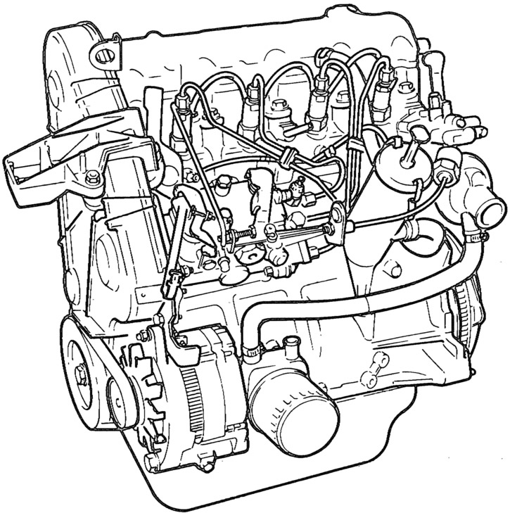
Fig. 9-25. External appearance of the DHW engine (XUD-9SD).
Disconnect the crankcase ventilation hose from the air filter (Fig. 9-26), unscrew the three fastening nuts, remove the air filter cover with the gasket and take out the filter element. Remove the air filter housing with the gasket by unscrewing the four nuts fastening it to the intake pipe.
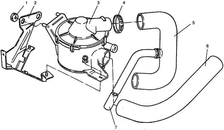
Fig. 9-26. Air filter:
1 - rubber support; 2 - filter mounting bracket; 3 - filter; 4 - clamp; 5 - air duct; 6 - cold air intake; 7 - crankcase ventilation hose.
Disconnect the fuel supply and return hoses from the high-pressure fuel pump.
Using a spanner, loosen the nuts securing the muffler inlet pipe to the exhaust manifold.
Disconnect the fuel supply cable from the high pressure pump by pressing the ball end with a flat screwdriver.
Disconnect the cable from the fuel injection advance angle adjustment (FIAA) lever by unscrewing the fastening screw and pressing the tip.
Remove the gearbox as described in the "Gearbox" chapter of the Repair Manual.
The original source is located on the website www.VazBook.ru
Hang the TCO-3/379 hoist crossmember and secure the engine on the right side by the bracket installed on the front exhaust manifold mounting stud, and on the left side by the clutch housing mounting hole. Slightly tighten the hoist chain, unscrew the nuts securing the cushions 2 (Fig. 9-27) of the front engine mount to the front suspension crossmember and remove the engine from the compartment.
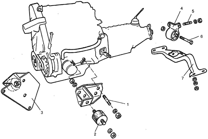
Fig. 9-27. Engine mount:
1 - left engine mount bracket mounting stud; 2 - pillow; 3 - right engine mount bracket complete with cushion; 4 - bracket with support of rear engine mount; 5 - hairpin; 6 - bolt; 7 - rear engine mount cross member.
Remove the starter heat shield and the starter. Loosen the clutch mounting bolts and remove it.
When installing the engine, the following operations must be performed:
- install coolant hoses, connectors and clamps;
- check the condition of the radiator (scale, leak, damage);
- check the functionality of the radiator cooling fan;
- check the seal and the radiator cap valve;
- install new air and fuel filter elements;
- fill the engine with oil;
- adjust the controls;
- fill the cooling system, removing air locks;
- start and warm up the engine;
- adjust idle speed;
- check the lubrication and cooling systems for leaks.
Pay special attention to the connection of the engine to the gearbox: the primary shaft must fit precisely into the splines of the driven clutch disc.