
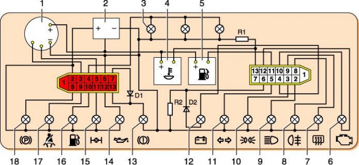
Wiring diagram of the instrument cluster from 1996 (inside view): 1 - tachometer; 2 - voltage stabilizer; 3 – a lamp of illumination of a combination of devices; 4 - coolant temperature gauge; 5 - fuel gauge; 6 – a control lamp of a control system of the engine; 7 – a control lamp of heating of back glass; 8 – a control lamp of antifog light; 9 – a control lamp of a high beam of headlights; 10 – a control lamp of external illumination; 11 – a control lamp of indexes of turn; 12 – a control lamp of a charge of the accumulator battery; 13 – a control lamp of level of a brake liquid; 14 – a control lamp of pressure of oil; 15 – a control lamp of blocking of differential; 16 – a control lamp of a reserve of fuel; 17 – a control lamp of seat belts; 18 – a control lamp of a parking brake; D1, D2 - diodes IN4002; R1 - resistor 470 Ohm, 0.25 W; R2 - resistor 51 ohm, 5 watts.
The coolant temperature gauge works in conjunction with a sensor screwed into the cylinder head. The sensor has a thermistor (resistor that changes its resistance with temperature).
Data for checking the coolant temperature gauge sensor
| Temperature,°С | Sensor voltage, V | Sensor resistance, Ohm |
| 30 | 8 | 1350–1880 |
| 50 | 7,6 | 585–820 |
| 70 | 6,85 | 280–390 |
| 90 | 5,8 | 155–196 |
| 110 | 4,7 | 87–109 |
Data for checking the coolant temperature gauge
| Pointer arrow position (at a voltage in the on-board network 13–14 V) | Temperature sensor resistance, Ohm |
| At the beginning of the scale | 640–1320 |
| At the beginning of the red zone | 77–89 |
| At the end of the red zone | 40–50 |
If the pointer needle is constantly at the beginning of the scale, with the ignition on, disconnect the wire from the sensor and through a 20–50 Ohm resistor (light bulb 4–5 W, relay coil) connect it with «weight». If the arrow deviates, the sensor is faulty. If the arrow does not deviate, remove the instrument cluster, disconnect the red block from it and, with the ignition on, connect the plug through a 20–50 Ohm resistor «13» white pads with «weight». If the arrow is now deviated - the circuit is faulty «sensor - pointer». If not, the pointer or its power circuit is faulty.
If the pointer is constantly in the red zone, with the ignition on, disconnect the wire from the sensor. If the arrow deviated to the beginning of the scale, the sensor is faulty, if not, the wire closes to «mass» Or the pointer doesn't work. The latter can be checked by disconnecting the white block from the instrument cluster. At the same time, a correct pointer (with the ignition on) the arrow should be at the beginning of the scale.
The fuel gauge works in conjunction with a sensor installed in the fuel tank. The sensor is a rheostat with a nichrome wire resistor. The movable contact of the rheostat is moved by a lever with a float. At the end of the lever there is an additional contact that closes the circuit of the fuel reserve indicator lamp when 4-6 liters of gasoline remain in the tank.
Data for checking the fuel gauge sensor
| Fuel level | Sensor resistance, Ohm |
| empty tank | 250±12 |
| half full | 66±6 |
| Full tank | 20±3 |
Data for checking the fuel gauge
| Pointer arrow position (at a voltage in the on-board network 13–14 V) | Sensor resistance, Ohm |
| At the beginning of the scale | 238–262 |
| Middle of the scale | 59–71 |
| At the end of the scale | 17–23 |
If the pointer is constantly at the beginning of the scale (shows an empty tank), with the ignition on, disconnect the pink wire from the sensor and connect it to «weight». If the arrow deviates to the end of the scale, the sensor or the circuit connecting it to «weight». If the arrow does not deviate, remove the instrument cluster, disconnect the white block from it and, with the ignition on, through a 20–50 Ohm resistor (light bulb 4–5 W, relay coil) connect her plug «11» With «weight». If now the arrow has deviated, the circuit is faulty «sensor - pointer». If not, the pointer or its power circuit is faulty.
If the pointer needle constantly shows a full tank, with the ignition on, disconnect the wire from the sensor. If the arrow deviated to the beginning of the scale, the sensor is faulty, if not, the wire closes to «mass» Or the pointer doesn't work. The latter can be checked by disconnecting the white block of wires from the instrument cluster. At the same time, a correct pointer (with the ignition on) the arrow should be at the mark «0».
The tachometer and speedometer are checked on special stands. As a rule, disturbances in their operation are associated with the oxidation of contacts in the supply and control circuits, or (at the speedometer) with incorrect laying, or damage to the cable or its drive (see Troubleshooting).
In case of failure of control devices or their sensors, they are replaced.