
English Русский
Български
Беларускі
Український
Српски
Hrvatski
Română
Polski
Slovenský
Magyar
| Articles | Contacts | Sitemap |   
Repair and maintenance Lada Repair and maintenance Mazda Repair and maintenance Mitsubishi Repair and maintenance Toyota Repair and maintenance Land Rover Repair and maintenance Hyundai Repair and maintenance Nissan
VAZbook.ru


Main     1111   2101   2105   2106   2107   2109   2110   2115   2121  
VAZ-2121 (1977-1994) VAZ-21213 (1994-2006) VAZ-21214 (1994-2006)
  • Main
  • «Niva»
  • VAZ-21214
  • Electrical equipment
  • Engine electrics
  • Carburetor electromagnetic valve control system

Carburetor electromagnetic valve control system (VAZ-21214)

            0

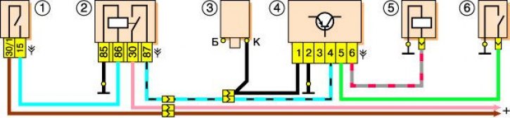
Wiring diagram of the carburetor electromagnetic valve control system: 1 – ignition switch; 2 –…

Wiring diagram of the carburetor electromagnetic valve control system: 1 – ignition switch; 2 – ignition relay; 3 – ignition coil; 4 – control unit;5 – electromagnetic valve; 6 – carburetor limit switch.


The carburetor solenoid valve control unit turns off the valve (interrupts fuel supply) when the crankshaft speed increases to 2100 min⁻¹ and turns on when the speed decreases to 1900 min⁻¹, if the carburetor limit switch is shorted to ground (the "gas" pedal is released). When the "gas" pedal is pressed (open circuit breaker) the valve is on regardless of the crankshaft speed (fuel is supplied). Power is supplied to the control unit only when the ignition is on, so when the ignition is turned off, the valve is also turned off (regardless of the position of the carburetor limit switch), which prevents the engine from self-igniting (solenoid valve normally closed).

To check the operation of the control unit, connect a voltmeter in parallel with the winding of the electromagnetic valve (the valve operation can be determined by its knocking, without connecting a voltmeter). Disconnect the wire from the carburetor limit switch and connect it to ground. Start the engine and, gradually increasing the crankshaft speed, monitor the voltmeter readings. After starting the engine, the voltmeter should show at least 10 V (the valve is open), and at about 2100 rpm the voltage should drop sharply to a value of no more than 0.5 V (valve closed). After that, slowly reduce the engine speed, at about 1900 rpm the voltage should increase abruptly to the previous value (valve open). Set the speed within 2200–2300 rpm (the valve is closed) and disconnect the carburetor limit switch wire from the ground – the valve should open.

See Removing the Solenoid Valve. Removal and checking the electromagnetic valve.


This article is available at russian, bulgarian, belarusian, ukrainian, serbian, croatian, romanian, polish, slovak, hungarian
The text was reviewed by the specialist: Grigory Vologodtsev

Share with friends:

Previous articles
VAZ-21214: Engine electrics
Next articles

Disassembling the starter 35.3708
Disassembling the starter 5722.3708
Removal the starter
Description of the starter design
Removal the generator 371.3701
Removal the carburetor electromagnetic valve control unit
Removal the carburetor air damper cover indicator lamp and its switch

More articles from other manuals on VAZ cars:
➠ Carburetor electromagnetic valve control system VAZ-2105 (1979-2010)
➠ Wiring diagram of the control system of the electromagnetic… VAZ-2106 (1976-2006)
➠ Carburetor electromagnetic valve control system VAZ-2109 (1984-1997)
➠ Description of the design of the fuel system of a carburetor… VAZ-2107 (1982-2012)
➠ Carburetor fuel system with semi-automatic start and warm-up VAZ-2110 (1995-2007)
Link in different formats to this page


Visitor comments

No comments yet


How much will 38 + 32 ?


VAZ-2121 (1977-1994) 
  • General information
  • Vehicle device
  • Car VAZ-21219
  • Power unit
  • Engine repair
  • Cooling system
  • Lubrication system
  • Supply system
  • Transmission
  • Clutch
  • Car gearbox
  • Transfer case
  • Cardan gear
  • Rear axle and gearbox
  • Front axle
  • Chassis
  • Front suspension
  • Rear suspension
  • Steering
  • Brake system
  • Body
  • Exterior
  • Interior
  • Doors and windows
  • Electrical equipment
  • Equipment and devices
  • Headlights and lighting
  • Engine electrics


VAZ-21213 (1994-2006) 
  • General information
  • Vehicle device
  • User manual
  • Power unit
  • Engine repair
  • Cooling and lubrication system
  • Supply system
  • Transmission
  • Clutch
  • Car gearbox
  • Transfer case
  • Cardan gear
  • Rear axle and shafts
  • Front axle and wheel drive
  • Chassis
  • Wheel suspension
  • Steering
  • Brake system
  • Body
  • Exterior
  • Interior
  • Electrical equipment
  • Engine electrics
  • Equipment and devices


VAZ-21214 (1994-2006) 
  • General information
  • Vehicle information
  • Troubleshooting
  • Power unit
  • Engine repair
  • Cooling system
  • Fuel system (carburetor)
  • Fuel system (injector)
  • Ignition system
  • Control system
  • Exhaust system
  • Transmission
  • Clutch
  • Car gearbox
  • Transfer case
  • Cardan gear
  • Front axle
  • Rear axle
  • Chassis
  • Front suspension
  • Rear suspension
  • Steering
  • Brake system
  • Body
  • Exterior
  • Interior
  • Doors, covers and windows
  • Ventilation and heating
  • Electrical equipment
  • Equipment and devices
  • Headlights and lighting
  • Engine electrics
  • Electrical circuits


VAZbook.ru © 2017 · Mobile version · Contact with administration · Sitemap: EN BG BY UA RS HR RO PL SK HU · Site search · News and articles VAZ-1111 · VAZ-11113 · VAZ-2101 · VAZ-21011 · VAZ-2104 · VAZ-2105 · VAZ-21051 · VAZ-2106 · VAZ-21061 · VAZ-2107 · VAZ-21099 · VAZ-2109 · VAZ-2108 · VAZ-2110 · VAZ-2112 · VAZ-2114 · VAZ-2115 · VAZ-2121 · VAZ-21213 · VAZ-21214 ·
The site stores technical data using cookies to improve the service.