
Attention! We carry out work on a viewing ditch or a lift.
Remove the oil pan protection plate and the right engine mudguard (see Removal of the protection plate of the oil pan and mudguard of the carburetor engine).
Remove the water pump drive belt (see Tension adjustment and replacement of the coolant pump drive belt).
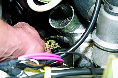
Using pliers, loosen the clamp of the rubber air intake.
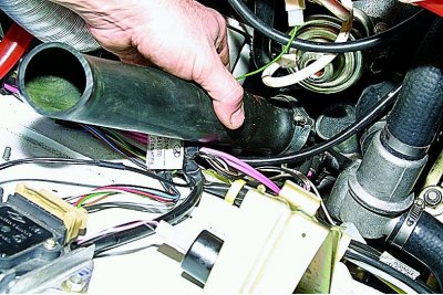
We remove the air intake from the nozzle of the protective casing of the generator.
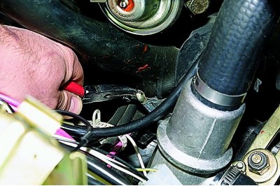
Disconnecting the output «61» generator.
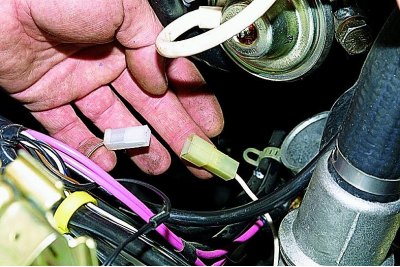
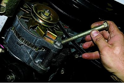
Sliding rubber cover, keyed «on 10» unscrew the nut securing the wires to the output extension «30» generator.
We remove the wires.
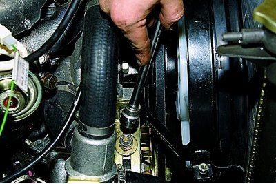
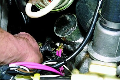
head «at 17» unscrew the nut securing the generator to the tension bar.
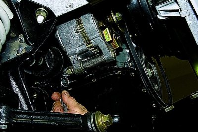
ring wrench «at 19» unscrew the nut of the bolt securing the generator to the bracket..
... and remove the bolt.
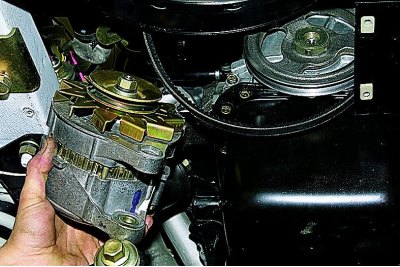
We take out the generator from a motor compartment downwards.
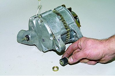
Rubber and metal bushings are installed in the eye of the rear cover of the generator.
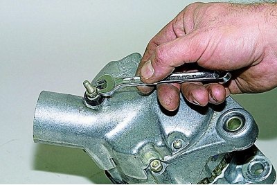
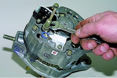
key «on 10» unscrew the nut of the insulating bushing of the output extension «30» generator.
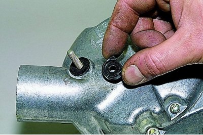
Taking the outside..
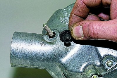
...and internal insulating sleeves.
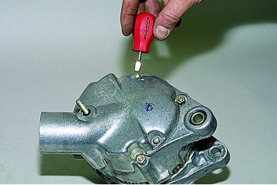
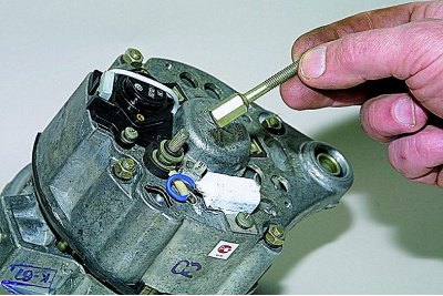
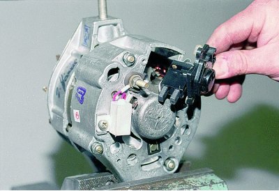
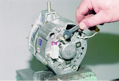
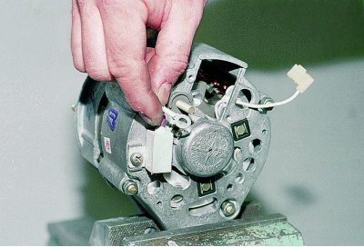
Using a slotted screwdriver, unscrew the two screws securing the protective cover to the generator.
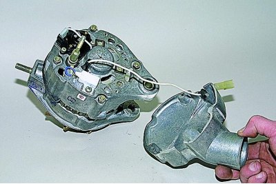
Remove the protective cover.
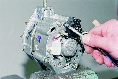
Disconnect the wire from the output «61».
key «on 10» unscrew the extension cord «30».
We remove the extension.
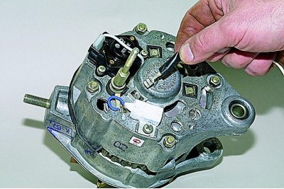
Disconnect the wire from the voltage regulator.
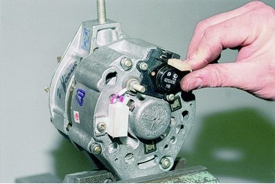
Using a Phillips screwdriver, unscrew the two screws securing the voltage regulator and brush holder.
Remove the voltage regulator with brush holder.
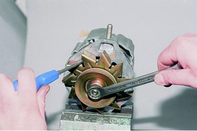
key «at 19» Loosen the alternator pulley nut. The rotor can be blocked from turning with a screwdriver (do not bend the impeller).
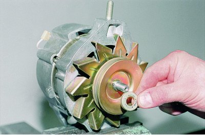
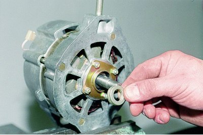
We remove the washer from the shaft,..
... pulley halves,..
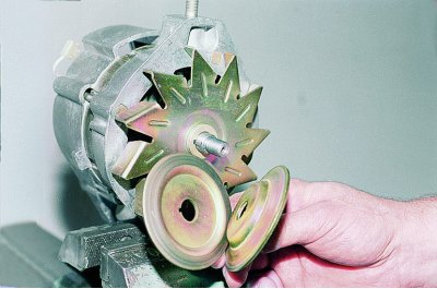
... spacer,..
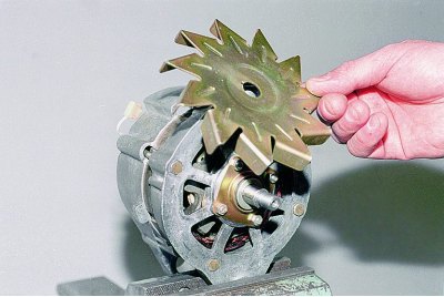
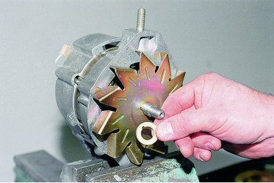
... an impeller.
We pry with a screwdriver and remove the segment key,..
... under which there is a washer without a keyway.
key «on 10» unscrew the nut securing the capacitor terminal.
We remove the terminal and, having unscrewed the screw with a Phillips screwdriver, dismantle the capacitor.
With sharply sharpened scriber or paint, we mark the relative position of the covers and the stator for subsequent assembly.
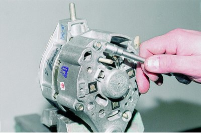
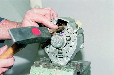
head «on 10» unscrew the four nuts of the coupling bolts.
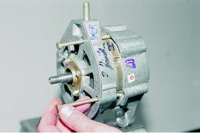
We take out the bolts.
Remove the front cover.
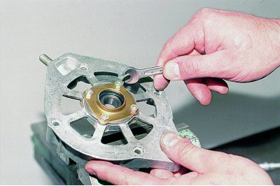
To replace a bearing with a wrench «for 8» on the outside of the cover, unscrew the four nuts of the screws securing the plates.
We remove the plates with screws.
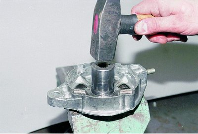
Tool head of suitable size (or pipe section) press the bearing out of the cover.
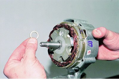
A thrust ring is located on the rotor shaft.
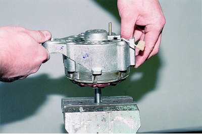
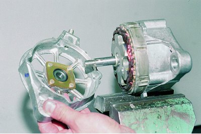
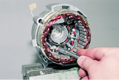
We screw a nut onto the thread of the shaft, clamp it in a vise and jerk off the back cover with the stator.
If it is difficult to remove the rotor, tap on its end with a soft metal drift through the voltage regulator window.
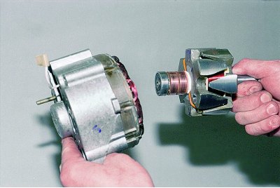
Disconnect the rotor and stator.
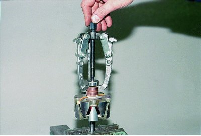
With a puller we press the bearing from the rotor shaft.
head «for 8» unscrew the three nuts securing the stator terminals to the rectifier unit.
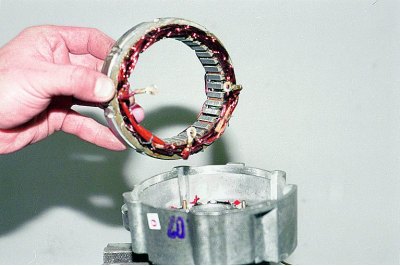
Pry off with a screwdriver and remove the stator.
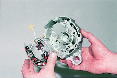
Remove the rectifier.
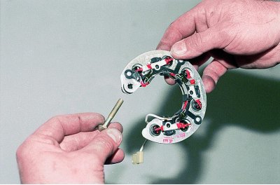
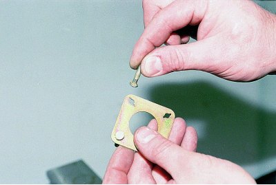
We take out the contact bolt from the rectifier block.
We assemble the generator in reverse order. We put the nuts of the screws for fastening the bearing plates of the front cover on the thread sealant. We press new bearings into the front cover and onto the rotor shaft with suitable pipe sections.