
Drain the oil from the transfer case and clean it of dirt.
Loosen the driveshaft flange nut (see Replacing the shaft seals of the transfer case).
Similarly, we loosen the nuts of the other two flanges.
Remove the speedometer gear housing (see Removing the gear housing of the speedometer drive and the speed sensor of the VAZ-21214 car (speedometer drive gear housing VAZ-21213)).
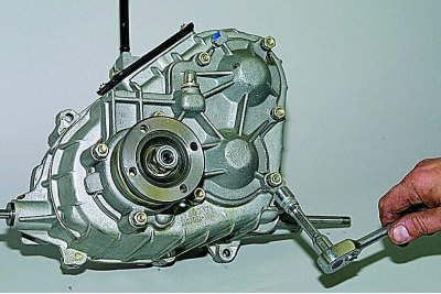
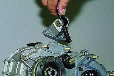
head «at 13» unscrew the five nuts of the front axle drive housing.
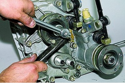
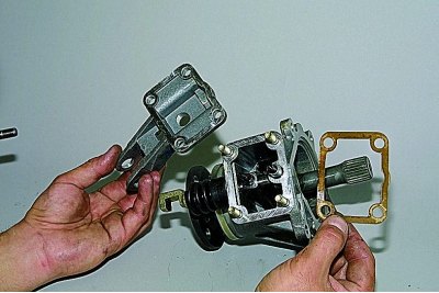
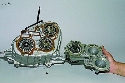
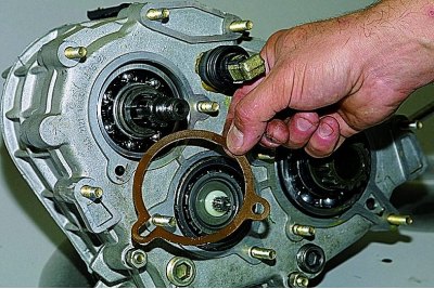
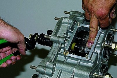
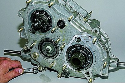
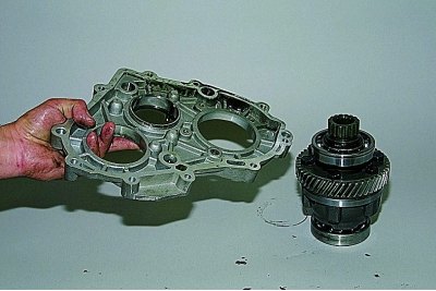
Prying off the crankcase with a screwdriver for the tides,..
...remove it..
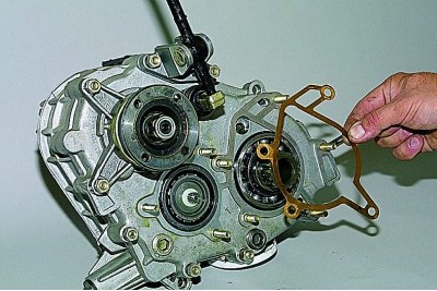
...and a gasket.
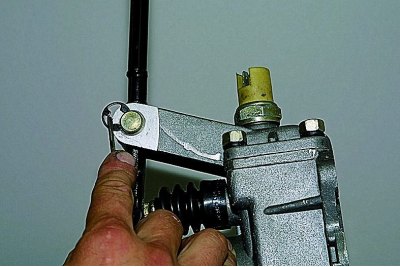
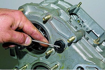
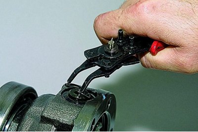
Pry off the lock washer with a screwdriver,..
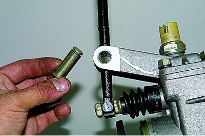
... take out the axle of the differential lock lever (if difficult, knock out with a soft metal drift).
Remove the differential lock lever and plastic axle bushings.
Remove the differential lock warning light switch (see Replacement of the switch of a control lamp of blocking of differential).
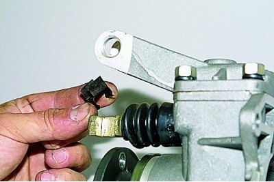
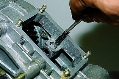
Remove the lever spring from the stem of the differential lock fork.

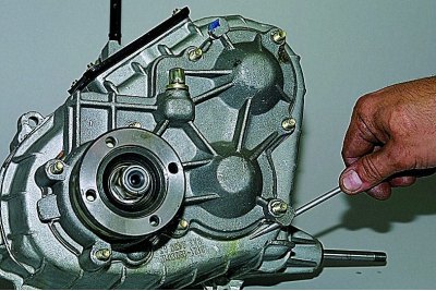
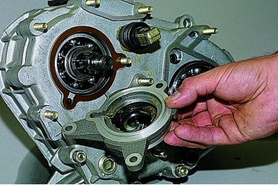
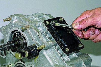
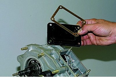
head «at 13» unscrew the four nuts securing the front axle drive housing cover.
Remove cover and gasket.
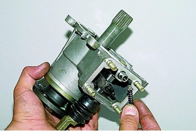
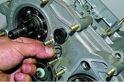
We take out the spring and shake out the retainer ball from the crankcase socket.
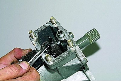
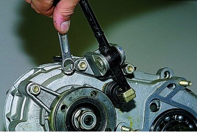
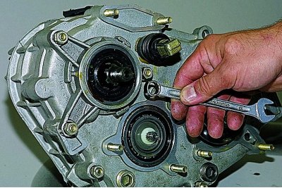
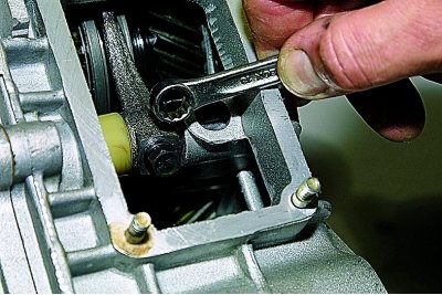
ring wrench «on 10» unscrew the locking bolt of the differential lock clutch fork.
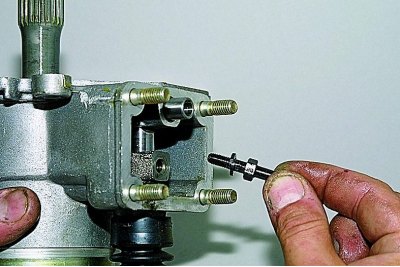
We take out the bolt with the spring washer.
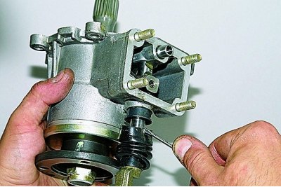
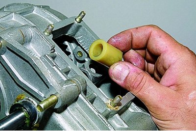
We pry off the protective cover of the differential lock fork rod with a screwdriver..

... and take out the stock with a cover.
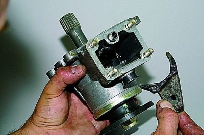
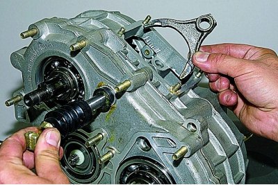
Taking out the fork..
...and a differential lock clutch.
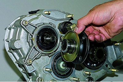
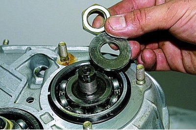
We unscrew the previously loosened flange fastening nut to the end and remove the washer.
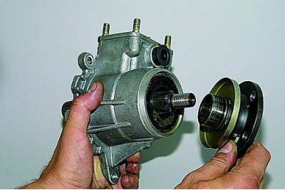
We remove the flange.
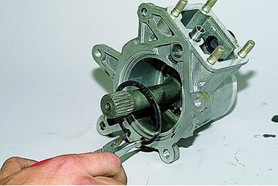
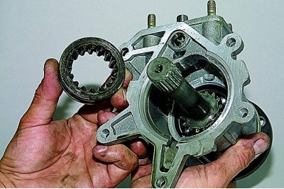
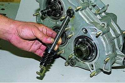
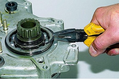
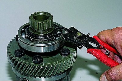
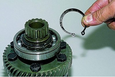
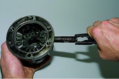
Squeezing with tongs, we take out the retaining ring of the bearing of the front axle drive shaft.
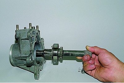
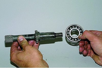
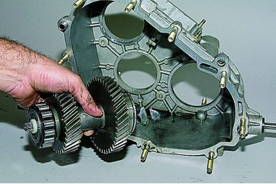
We take out the shaft assembly from the crankcase.
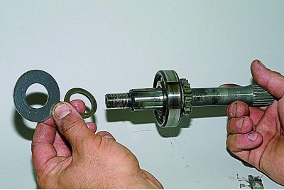
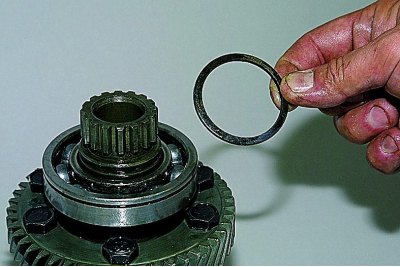
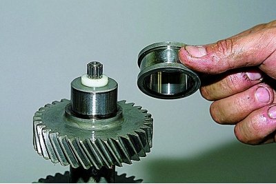
Remove the oil deflector and thrust ring from the front end of the shaft.
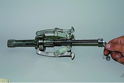
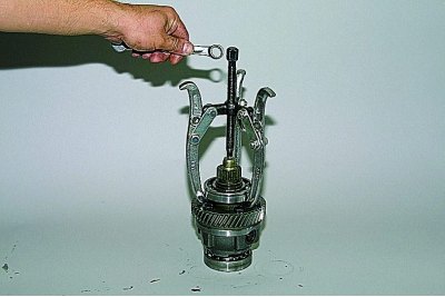
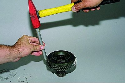
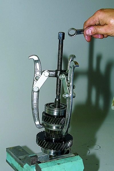
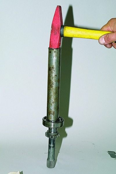
Having hooked the outer ring of the bearing with a three-legged puller,..
... compress the bearing.
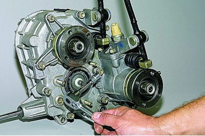
head «at 13» unscrew the eight nuts securing the rear cover to the transfer case housing.
Prying off with a screwdriver..
... remove the cover assembly with the rear axle drive shaft..
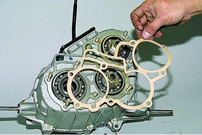
...and a gasket.
We take out the rear axle drive shaft from the rear cover and disassemble it in the same way as the front crankcase shaft.
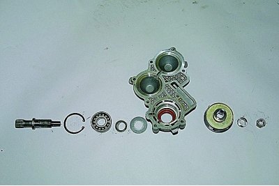
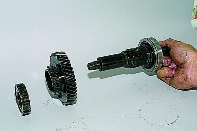
Details of the rear axle drive shaft and rear cover.
key «at 13» unscrew the two nuts securing the gear lever bracket to the transfer case housing..
... and remove the gearshift bracket with the lever.
Disconnect the gearshift lever from the bracket in the same way as removing the differential lock lever.
Having finally unscrewed the nut of the drive shaft flange,..
... remove the flange.
key «at 13» loosen three screws..
... and remove the front bearing cap of the input shaft.
The connection is sealed with a gasket.
key «on 10» unscrew the four nuts securing the hatch.
We remove the hatch and gasket.
Remove the lever spring from the shift fork rod (similar to the one shown in photo 9) and move the stem cover (as shown in photo 15).
Inside the hatch with a spanner wrench «on 10» unscrew the bolt securing the fork to the stem.
To prevent the ball and detent spring from popping out,..
... cover the hole with your finger and gradually pull out the stem with pliers.

In this case, the retainer ball falls out through the side opening of the crankcase.
Remove the retainer spring with tweezers.
Pulling the stem further, remove the gear shift fork..
...and a plastic spacer.
We take out the stock.
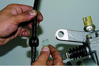
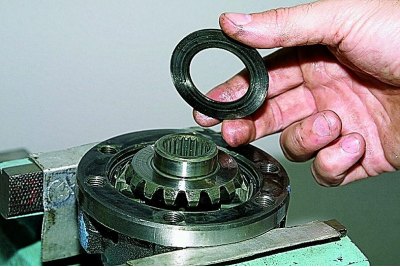
The shafts of the differential lock fork and the shift fork are sealed with rubber rings. Let's show their removal on the example of the ring of the gear fork rod.
Prying off with a screwdriver..
... take out the sealing rubber ring.
Loosen the nuts of the rear bearings of the drive and intermediate shafts.

ring wrench «at 27» we unscrew one of the nuts, keeping the shafts from turning by the other nut with a wrench or a head of the same dimension.
Remove the nut and washer.
We insert the propeller shaft mounting bolts into the flange holes and put the flange on the splines of the transfer case drive shaft.

We turn off the second nut, keeping the shafts from turning with a mounting blade inserted between the bolts.
Remove the nut and washer. Remove the drive shaft flange.

Remove the thrust ring of the front bearing of the drive shaft.
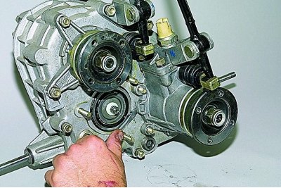
key «at 13» unscrew the three remaining nuts securing the front cover of the transfer case.
The remaining nuts of this cover were unscrewed when dismantling the cover of the front bearing of the input shaft, the front axle drive housing and the gear lever bracket.

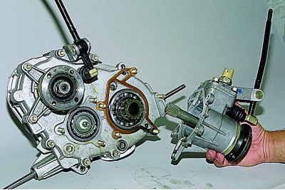
Remove the front cover of the transfer case with differential.
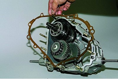
Remove the gasket from the transfer case housing studs.
Using pliers, remove the adjusting ring of the front bearing of the differential housing.
We disconnect the differential and the front cover of the transfer case.

We take out (or knock out through a soft metal drift) from the socket of the front cover, the outer ring of the front bearing of the intermediate shaft.
Using pliers, open the retaining ring of the front bearing of the differential housing..
...and take it off.
Remove the spring washer.
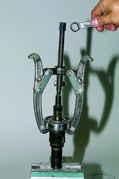
We install a suitable stop for the puller screw in the hole in the front differential housing..
...and a three-legged puller..
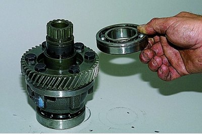
... compress the front bearing.
If necessary, remove the rear bearing in the same way.
We put marks on the front and rear differential housings so that during assembly they do not disturb the balance of the assembly.
Clamping the differential housing in a vise with soft metal jaws,..
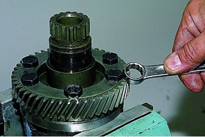
... with a spanner «at 17» unscrew the six bolts securing the driven gear, front and rear differential housings.
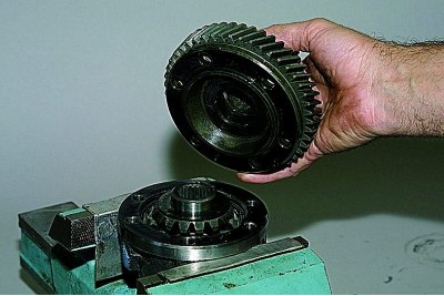
Separate the front and rear differential housings.
In this case, the driven gear remains on the front housing.
We knock it off the body through a soft metal drift.
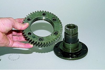
Disconnect the driven gear and the front differential case.
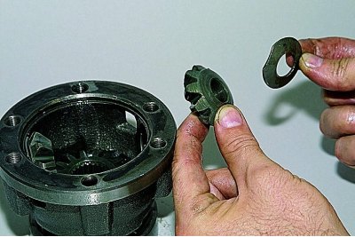
Remove the support washer from the front axle drive gear..

... and take out the gear itself.
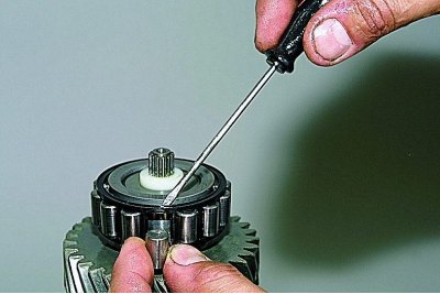
Open the circlip of the pinion axle with pliers and remove it.

Remove the spring washer of the axis of the satellites.
Having hooked with pliers on another retaining ring, we take out the axis of the satellites.
We take out the support washer and satellite from the rear differential housing.
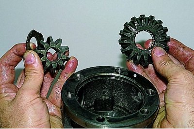
Having taken out the second satellite and its washer, we remove the rear axle drive gear.
To remove the input and intermediate shafts..
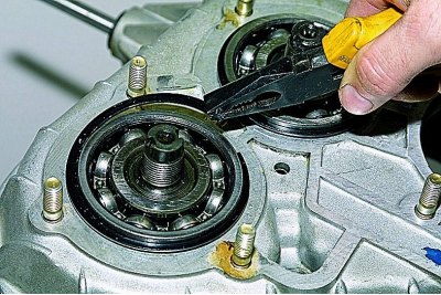
... use pliers to remove the adjusting ring of the rear bearing of the drive shaft.
Similarly, we dismantle the ring of the rear bearing of the intermediate shaft.

We remove the drive shaft from the crankcase...
...and intermediate shaft.
We clamp the splined part of the drive shaft in a vise with soft metal jaw pads,..
... and, hooking the paws of the puller on the gearshift clutch,..

... remove the rear bearing, bushing, low gear and clutch.
Remove the clutch hub and top gear from the shaft.
With a puller we press the front bearing of the drive shaft.
Remove the rollers from the front bearing of the intermediate shaft with a screwdriver..

... and remove the separator.
We clamp the intermediate shaft in a vise with soft metal jaw pads.
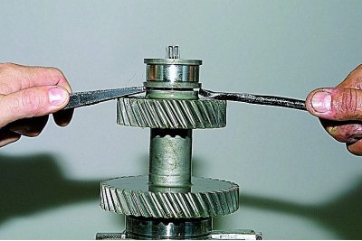
Prying with two mounting blades, we compress the inner ring of the front bearing..
...and take it off.
We remove the rear bearing of the intermediate shaft in the same way as the front bearing of the input shaft.
We assemble the transfer case in reverse order.
When assembling the center differential, we combine the marks on its housings.
We install the spring washer on the axis of the satellites from the side of the blind hole at the end of the axis.
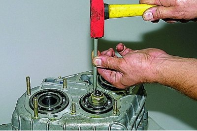
We press with suitable pipe sections..
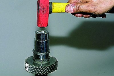
... the inner race of the intermediate shaft front bearing,..
... front axle drive shaft bearing (the pipe rests on the inner ring) …
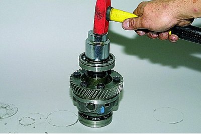
...and differential bearings.
In the same way, we press on the bearing of the rear axle drive shaft, the rear bearing of the intermediate shaft, the front and rear bearings of the input shaft.
We install the drive and intermediate shafts in the transfer case housing at the same time.
Lubricate all gaskets with a thin layer of silicone sealant.
Having tightened the nuts of the rear bearings of the drive and intermediate shafts to the set torque, we lock the nuts by pressing their shoulders into the grooves of the shaft shanks.
Fill with oil after assembly (see Change of oil).
Helpful Hints
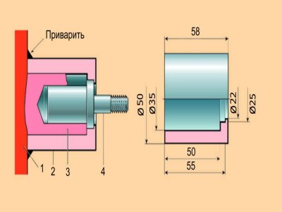
Stud attachment point: 1 - crankcase; 2 - bushing; 3 - the rest of the boss; 4 - hairpin
Repair of fastening of a hairpin of a crankcase of a distributing box
At the transfer case, the right one sometimes bursts (long) a boss, into which a special pin is pressed, which fastens the box to the bracket. For repair, you can turn the duralumin bushing, as shown in the figure, file down all the ribs on the remaining part of the boss and file its outer diameter to fit the bushing tightly. Having installed the fastening stud in the hole, you need to press the sleeve all the way and weld it around the perimeter to the box body.