
Generator
The Valeo generator is supplied with the engine. The generator connection diagram is shown in fig. 9-34.
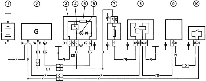
Pic. 9-34. Generator connection diagram:
1 - battery; 2 - generator; 3 - instrument cluster; 4 - electronic tachometer; 5 - resistor 50 Ohm, 5 W; 6 - control lamp of the battery discharge; 7 - fuse box; 8 - ignition relay; 9 - APS control unit; 10 - ignition switch.
The voltage to excite the generator when the ignition is turned on is supplied to the output «IN-» generator through the control lamp 6. After starting the engine, the current does not pass through the control lamp, and it does not light up. Conclusion «W» generator is used to output a voltage signal to the electronic tachometer 4.
Starter
The Valeo starter is supplied with the engine. The starter connection diagram is shown in fig. 9-35.
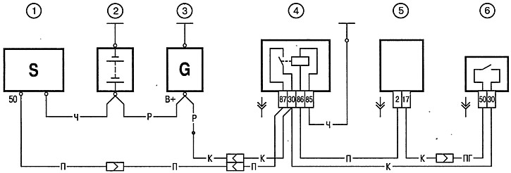
Pic. 9-35. Starter connection diagram:
1 - starter; 2 - battery; 3 - generator; 4 - ignition relay; 5 - APS control unit; 6 - ignition switch.
Engine management system
The connection diagram of the engine management system is shown in fig. 9-36. The device, operation and diagnostics of the system are described in detail in a separate Diesel Engine Diagnostics Manual developed by «Peugeot».
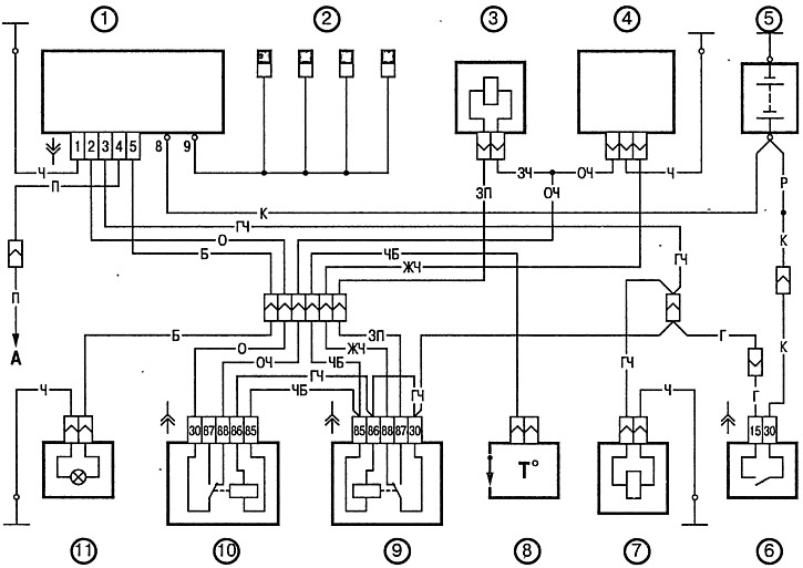
Pic. 9-36. Connection diagram of the engine management system:
1 - control unit for glow plugs; 2 - glow plugs; 3 - solenoid recirculation valve; 4 - fuel pump; 5 - battery; 6 - ignition switch; 7 - cutter; 8 - thermal switch; 9 - relay of the electromagnetic recirculation valve; 10 - thermal switch relay; 11 - control lamp for glow plugs.