
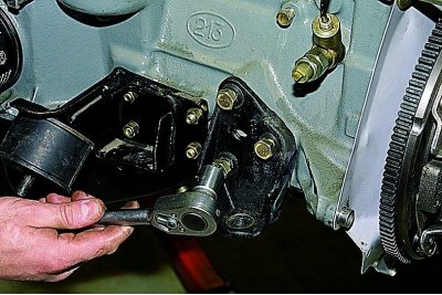
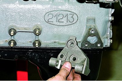
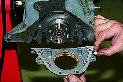
head «at 17» unscrew the three bolts securing the front axle gearbox bracket to the cylinder block...
...and remove the bracket.
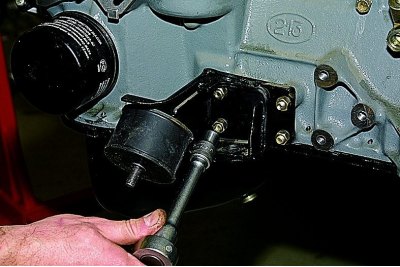
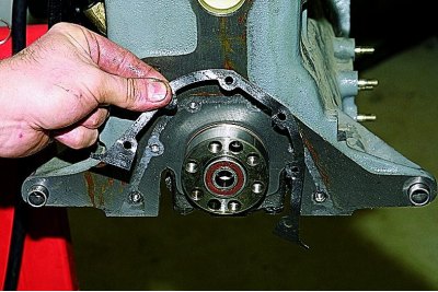
head «at 13» unscrew the four nuts securing to the cylinder block of the bracket of the left support of the power unit...
...and remove the bracket assembly with the pillow.
After removing the brackets on their mounting studs and threaded holes in the cylinder block, we mount the plate of the dismantling stand and fix the engine on the stand. Removing the clutch (see Replacing the driven and master clutch discs).
Remove flywheel and clutch housing cover (see Replacement of a back epiploon of a cranked shaft).
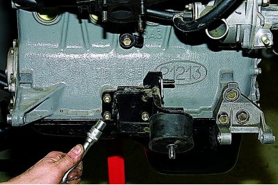
head «at 13» unscrew the four nuts securing the bracket of the right support of the power unit to the cylinder block...
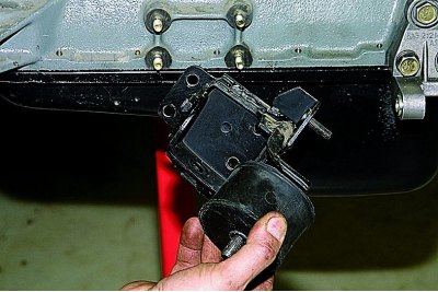
...and remove the bracket with the pillow.
head «at 17» unscrew the three bolts securing the generator bracket to the cylinder block...
...and remove the bracket.
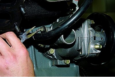
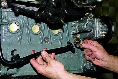
Using round-nose pliers, we loosen the clamp fastening to the branch pipe of the outlet pipe of the radiator of the heater of the hose for draining the coolant from the throttle assembly (VAZ-21214 engine) or from the carburetor heating unit (VAZ-21213).
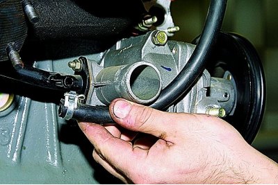
Remove the hose from the outlet tube.
head «on 10» unscrew the two nuts securing the flange of the outlet pipe of the heater radiator to the coolant pump housing.
Loosen the nut securing the tube bracket to the exhaust manifold (see Replacing the gasket of the intake pipe and exhaust manifold of the injection engine),...
... remove the outlet pipe of the heater radiator and its sealing gasket.
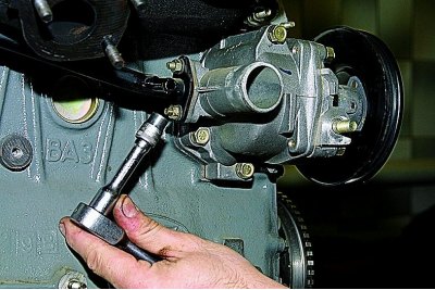
head «at 13» unscrew the three bolts securing the coolant pump to the cylinder block...
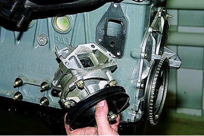
... and remove the coolant pump assembly and its gasket.
On an injection engine, we dismantle the cylinder head assembly with the receiver, intake pipe and exhaust manifold (see Removal and disassembly of the injection engine cylinder head).
On a carburetor engine, remove the cylinder head assembly with the carburetor, intake pipe and exhaust manifold (see Removal and disassembly of the cylinder head of the carburetor engine).
We remove the oil separator of the crankcase ventilation system, the crankcase pan and the oil pump (see relevant sections).
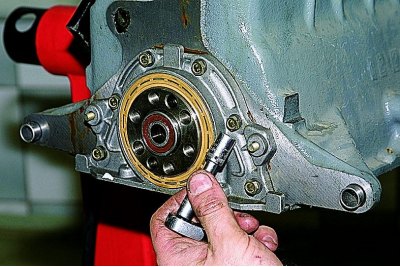
head «on 10» unscrew the six bolts securing the crankshaft rear oil seal holder to the cylinder block.
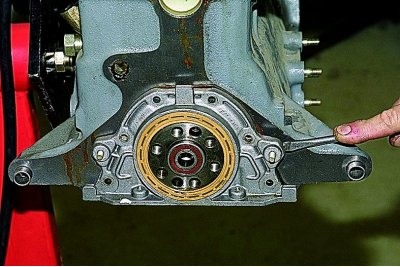
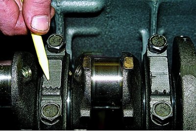
We pry off the holder of the rear oil seal with a screwdriver for the tides...
... and remove the holder assembly with the stuffing box.
Remove two special bolts from the grooves of the gland holder (with square heads) securing the clutch housing cover.
Remove the rear seal holder gasket.
Remove the camshaft drive cover, dismantle the chain, crankshaft sprocket, oil pump drive shaft, chain tensioner shoe (see relevant sections).
ring wrench «on 10» we unscrew the bolt of the bracket for the drain pipe of the oil separator of the crankcase ventilation system.
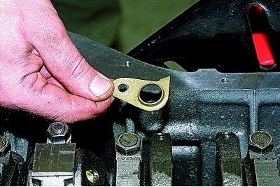
We remove the bracket.
head «at 14» unscrew the two nuts securing the connecting rod cap (the piston must be at BDC).
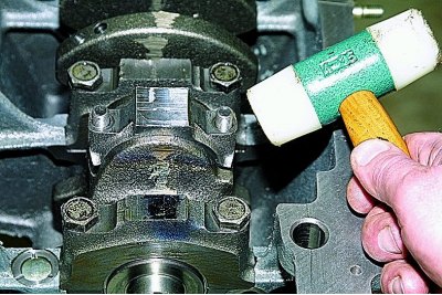
Having tapped on the side surfaces of the cover with a hammer with a plastic striker,...
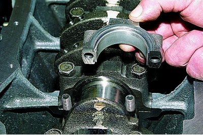
... remove the connecting rod cover.
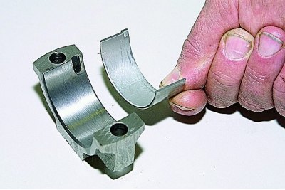
Remove the lower connecting rod bearing from the cover.
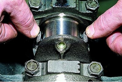
Leaning on the ends of the rods of the connecting rod bolts, we shift the lower head of the connecting rod from the connecting rod journal of the crankshaft.
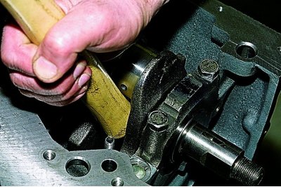
Resting the wooden handle of the hammer against the connector of the lower head of the connecting rod, we push the piston into the cylinder...
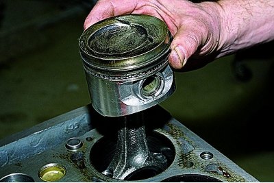
... and remove the piston with the connecting rod from the cylinder.
Remove the upper bearing shell from the connecting rod head.
Similarly, we remove the pistons with connecting rods from other cylinders.
Clamp the connecting rod in a vise with soft metal jaws.
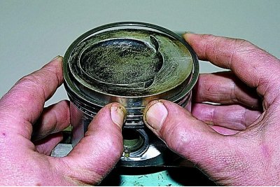
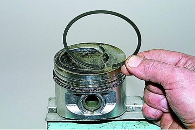
Fingers carefully (without much effort) release the upper compression ring...
...and remove the top compression ring.
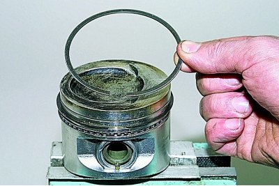
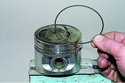
In the same way we shoot...
...lower compression ring,...
...two oil ring discs.
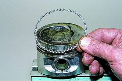
Remove the oil ring expander.
To remove the piston from the connecting rod...
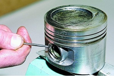
... pry off the piston pin circlip with a screwdriver...
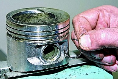
... and remove it from the annular groove of the piston.
In the same way, we take out the second locking ring of the finger.
Sliding the piston pin...
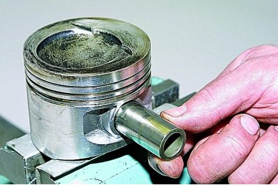
... remove it from the hole in the piston.
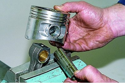
Remove the piston from the upper head of the connecting rod.
If some parts of the connecting rod and piston group are not damaged and slightly worn, they can be reused. Therefore, when disassembling, we mark the parts in order to install them in the previous cylinder.
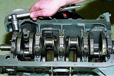
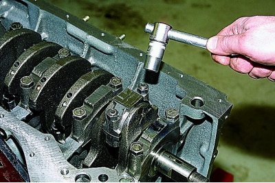
head «at 17» unscrew the two bolts securing the crankshaft main bearing cap.
Remove the main bearing cap.
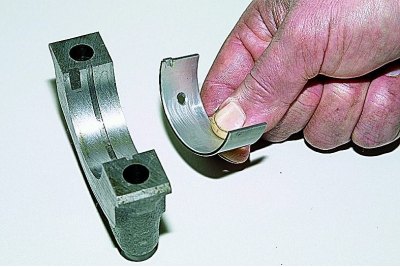
Remove the lower main bearing from the cover.
In the same way, remove four more main bearing caps.
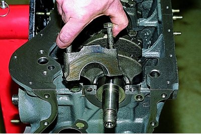
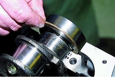
Remove the crankshaft from the cylinder block.

We take out the thrust half rings from the grooves of the rear support of the cylinder block.
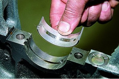
We take out from the supports of the cylinder block the upper loose leaves of the main bearings of the crankshaft.
After disassembling the engine, we thoroughly rinse with gasoline and clean the parts from carbon deposits to check their technical condition.
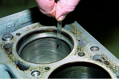
To determine cylinder wear...
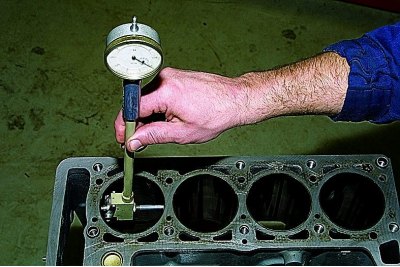
... with an inside gauge we measure the diameter of the cylinder in four belts and two planes (parallel and perpendicular to the axis of the crankshaft).
To determine piston skirt wear...
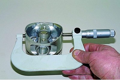
... with a micrometer we measure the diameter in a plane perpendicular to the axis of the piston pin, at a distance of 55 mm from the piston crown.
We measure the diameters with a micrometer...
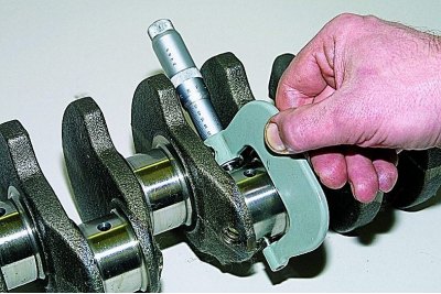
... connecting rod journals...
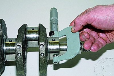
...and crankshaft journals.
We grind the crankshaft journals to the nearest repair size if their wear or ovality is more than 0.03 mm, and also if there are scuffs and risks on the necks.
After grinding the crankshaft journals...
... it is necessary to remove the plugs of the oil channels,...
...thoroughly rinse the channels to remove abrasive residues and blow with compressed air.
We grind the crankshaft journals, remove and install new plugs at the service station.
We assemble the engine in reverse order.
We install new crankshaft bearing shells of nominal or repair size (after polishing necks).
In the first, second, fourth and fifth supports of the cylinder block, we install the upper shells of the main bearings with grooves,...
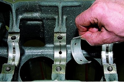
... and in the third support - an insert without a groove on the inner surface (same as in main bearing caps).
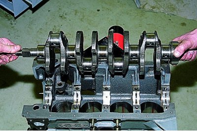
Lubricate the main bearing shells with engine oil and place the crankshaft in the bearings.
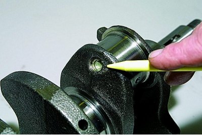
We insert thrust half rings lubricated with engine oil into the grooves of the fifth support.
On the front side of the fifth support, we install a steel-aluminum semi-ring, and on the back side - a metal-ceramic (yellow color).
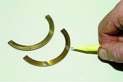
Surfaces of half rings with anti-friction coating (grooves are made on them) must face the thrust surfaces of the crankshaft.
We install the main bearing caps in accordance with the marks made on their outer surface (counting is done from the camshaft drive side).
In this case, the locks of the upper and lower shells of each main bearing must be located on the same side.
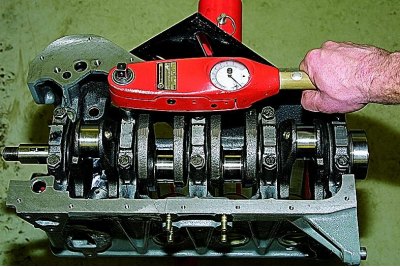
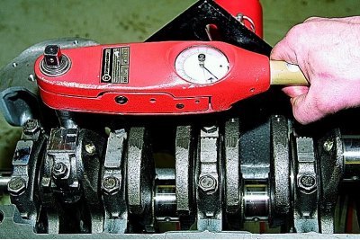
Tighten the main bearing cap bolts to the specified torque (see Tightening torques for threaded connections).
Pistons to cylinders are selected by class.
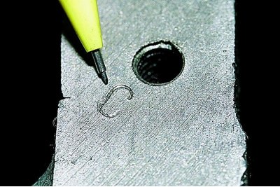
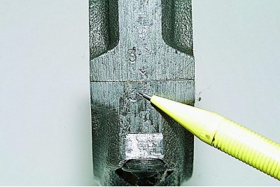
The cylinder diameter class, denoted by letters, is stamped on the bottom plane of the cylinder block (sump mounting plane).
Piston skirt diameter classes and piston pin bores are marked on the piston crown.
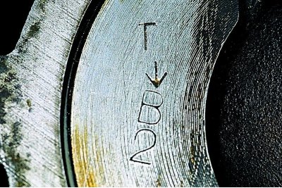
The arrow on the bottom of the piston when installing it in the cylinder must be directed towards the camshaft drive.
When assembling the connecting rod and piston group, it is necessary that the piston pin, lubricated with engine oil, enter the hole of the piston or connecting rod with hand force and not fall out of them when the pin is vertical.
To check the clearance in the piston ring lock, insert the ring into the cylinder and align the ring with the piston head.
With a set of flat feeler gauges, we check the clearance in the piston ring lock.
Lubricate the grooves on the pistons with engine oil.
We install rings on the pistons.
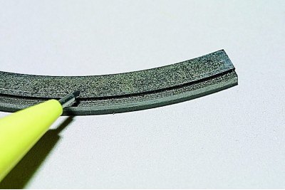
Install the lower compression ring with a groove («scraper») down.
If there is a mark on the ring near the lock «TOP» or «TOR», then the ring is set with the mark up.
The rings should turn freely in the grooves without jamming.
We arrange the rings as follows:
we orient the lock of the upper compression ring at an angle of 45°to the axis of the piston ring;
lock of the lower compression ring - at an angle of 180°to the axis of the lock of the upper ring;
oil scraper ring lock - at an angle of 90°to the axis of the lock of the upper compression ring (the joint of the expander is located on the side opposite to the lock).
Before installing ShPG parts, we lubricate the cylinders, pistons with rings and connecting rod bearings with engine oil.
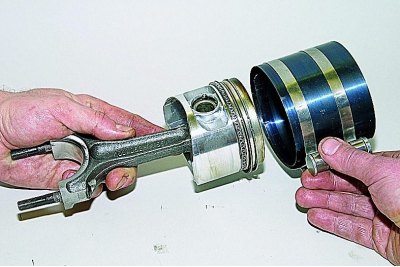
Before installing the piston in the cylinder, we put an adjustable mandrel on the piston...
... and, by tightening the mandrel, we compress the piston rings.
We install the piston with the connecting rod in the cylinder.
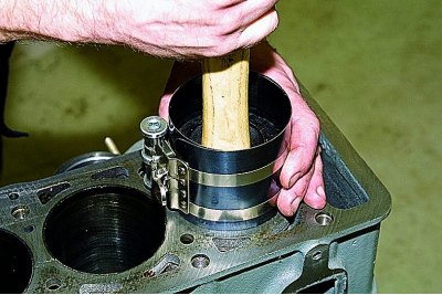
Resting the hammer handle on the bottom of the piston, we push it into the cylinder.
When installing the connecting rod cap, the number on the connecting rod and cap must match and be on the same side of the connecting rod.
Tighten the connecting rod nuts to the prescribed torque (see Tightening torques for threaded connections). Further assembly is carried out in the reverse order of disassembly. Replace gaskets and seals with new ones.
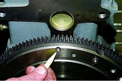
When installing the flywheel, orient it so that the installation (cone hole), located on the rear plane of the flywheel next to the ring gear, was located opposite the connecting rod journal of the fourth cylinder.