
Car anti-theft system
An automobile anti-theft system is installed on the VAZ-21215-10 car (APS) relay type APS-2R, consisting of a control unit 1 (pic. 9-37), system status indicator 2 and code keys 3. APS is an electronic unit that allows, in case of unauthorized access, to prevent the engine from starting by opening the necessary electrical circuits. The APS connection diagram is shown in fig. 9-38. In connection with the installation of an automobile anti-theft system, the schemes for switching on direction indicators and alarms have changed (pic. 9-39), windshield wiper and washer (pic. 9-40), wiper, washer and rear window heating element (pic. 9-41).
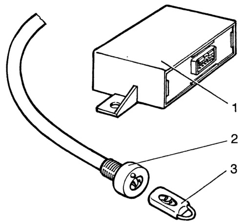
Pic. 9-37. Car anti-theft system:
1 - control unit; 2 - system status indicator; 3 - code key.
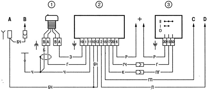
Pic. 9-38. Wiring diagram of car anti-theft system:
1 - system status indicator; 2 - APS control unit; 3 - ignition switch; And - to the switch of a plafond of lighting; B - to the ceiling lamp; C - to terminal «86» ignition relay; D - to terminal «86» starter relay.

Open large image in new tab »
Pic. 9-39. Scheme of switching on direction indicators and alarms:
1 - direction indicator lamps in the front lights; 2 - side direction indicators; 3 - ignition switch; 4 - APS control unit; 5 - ignition relay; 6 - fuse box; 7 - lamps of direction indicators in the rear lights; 8 - control lamp of direction indicators in the instrument cluster; 9 - relay-breaker for direction indicators and alarm; 10 - alarm switch; 11 - turn signal switch.
1 - direction indicator lamps in the front lights; 2 - side direction indicators; 3 - ignition switch; 4 - APS control unit; 5 - ignition relay; 6 - fuse box; 7 - lamps of direction indicators in the rear lights; 8 - control lamp of direction indicators in the instrument cluster; 9 - relay-breaker for direction indicators and alarm; 10 - alarm switch; 11 - turn signal switch.

Open large image in new tab »
Pic. 9-40. Windshield wiper and washer connection diagram:
1 - windshield washer motor; 2 - windshield wiper motor; 3 - ignition switch; 4 - APS control unit; 5 - ignition relay; 6 - fuse block; 7 - windshield wiper and washer switch; 8 - conditional numbering of plugs in the switch block; 9 - windshield wiper relay; 10 - conditional numbering of the plugs in the relay blocks and the windshield wiper motor.
1 - windshield washer motor; 2 - windshield wiper motor; 3 - ignition switch; 4 - APS control unit; 5 - ignition relay; 6 - fuse block; 7 - windshield wiper and washer switch; 8 - conditional numbering of plugs in the switch block; 9 - windshield wiper relay; 10 - conditional numbering of the plugs in the relay blocks and the windshield wiper motor.

Open large image in new tab »
Pic. 9-41. Scheme of switching on the cleaner, washer and rear window heating element:
1 - fuse box; 2 - switch for the rear window cleaner and washer; 3 - rear window washer motor; 4 - rear window cleaner motor; 5 - rear window heating element; 6 - relay for turning on the heating of the rear window; 7 - control lamp for heating the rear window; 8 - rear window heating switch; 9 - ignition switch.
1 - fuse box; 2 - switch for the rear window cleaner and washer; 3 - rear window washer motor; 4 - rear window cleaner motor; 5 - rear window heating element; 6 - relay for turning on the heating of the rear window; 7 - control lamp for heating the rear window; 8 - rear window heating switch; 9 - ignition switch.
Headlight cleaner and washer
The VAZ-21215-10 car is not equipped with cleaners and headlight washers.
Cooling fan motors
To drive the fans of the engine cooling system, two DC electric motors with excitation from permanent magnets of the MP 8019/37 type are used. The scheme of inclusion of electric motors is shown in fig. 9-42.
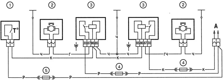
Pic. 9-42. Scheme of switching on the electric motors of the cooling system fans:
1 - sensor for turning on electric motors; 2 - fan motor; 3 - relay for switching on fan motors; 4 - 8 A fuse; 5 - 16 A fuse.
Electric motors are switched on by sensor 1 using auxiliary relays 3. The sensor is mounted in the right radiator tank. Sensor contact closure temperature (99±3) °С, and opening (94±3) °C. The relays are installed in the engine compartment and are bolted to the upper bulkhead reinforcement.
Electric motors are maintenance-free and should be replaced with new ones in case of failure.
Data for checking the electric motor:
- Rated shaft speed when the motor is loaded with an impeller, min-1 — 2600-2800
- Consumed current at the specified load and speed, no more than, A - 14
Instrument cluster
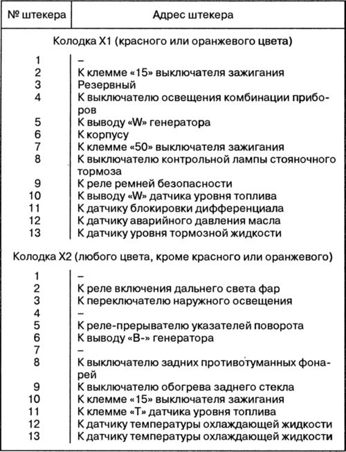
Instrument cluster includes: speedometer with trip odometer, coolant temperature gauge, fuel gauge, tachometer and 13 warning lights (pic. 9-43). The scheme of connections of a combination of devices is shown in fig. 9-44. The addresses of the output plugs of the instrument cluster are given in Table. 9-3.
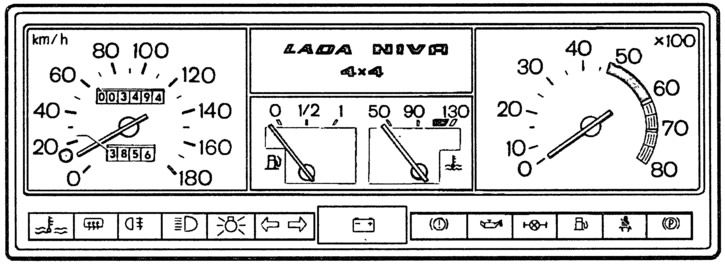
Pic. 9-43. Instrument combination.
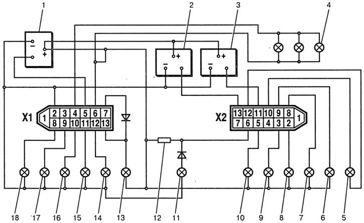
Pic. 9-44. Connection diagram of the instrument cluster:
1 - electronic tachometer; 2 - coolant temperature gauge; 3 - fuel gauge; 4 - instrument lighting lamps; 5 - warning lamp for engine overheating; 6 - control lamp for heating the rear window; 7 - control lamp of the rear fog lights; 8 - control lamp high beam headlights; 9 - control lamp for outdoor lighting; 10 - control lamp of direction indicators; 11 - control lamp of the battery discharge; 12 - resistor 50 Ohm, 5 W; 13 - control lamp for malfunction of service brakes; 14 - control lamp of emergency oil pressure; 15 - control lamp for blocking the interwheel differential; 16 - fuel reserve control lamp; 17 - warning lamp for unfastened seat belts; 18 - parking brake warning lamp. Block «X1» red or orange.
Table 9-3. Addresses of output plugs of the instrument cluster
Checking the coolant temperature gauge
The device operates in conjunction with a sensor installed in the cylinder head. With a sensor resistance of 640-320 ohms, the arrow should be at the beginning of the scale, with a resistance of 77-89 ohms, at the beginning of the red section of the scale, and with a sensor resistance of 40-50 ohms, it should deviate to the end of the red section of the scale.
Checking the fuel gauge
The device is used in tandem with a sensor installed in the fuel tank. The same sensor turns on the fuel reserve warning lamp if there are 4-6 liters of gasoline left in the tank. With a sensor resistance of 200-238 ohms, the arrow should be at the beginning of the scale, with a resistance of 59-71 ohms - in the middle of the scale, and with a sensor resistance of 17-23 ohms - it should deviate to the end of the scale (mark 1).
Checking the speedometer
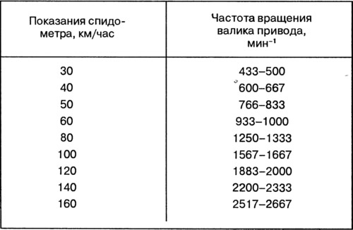
Check the speedometer by rotating its drive shaft at different speeds. Data for verification are given in table. 9-4.
Table 9-4. Data for checking the speedometer
Checking the tachometer
The principle of operation of the tachometer is based on measuring the frequency of repetition of voltage pulses in the excitation winding of the generator.
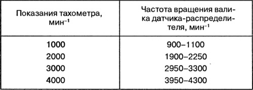
The tachometer is checked on a stand that simulates the ignition system of a car. Having connected the tachometer to the stand circuit in the same way as on a car, set the voltage in the primary circuit to 14 V and the gap in the stand arrester to 7 mm. Rotate the ignition distributor shaft at such a speed that the tachometer needle reaches one of the main divisions of the scale. At this point, check that the sensor-distributor shaft speed deviation is within acceptable limits (see table. 9-5).
Table 9-5. Data for checking the tachometer
Checking the fuel level sensor
When the tank is empty, the resistance of the sensor should be (250±10) Om, with the tank half full, - (66±6) Ohm, and with a full tank - (20±2) Ohm.