Check whether the working bevel is too worn or damaged. When grinding the working chamfer of the valve on a grinding machine, keep the chamfer angle equal to 45°30'±5' and make sure that the thickness of the cylindrical part of the valve disc after grinding is not less than 0.5 mm, and also that the exhaust valve does not have a layer of hard alloy deposited on the chamfer.
Valve guides
Check the clearance between the valve guides and the valve stem by measuring the diameter of the valve stem and the bore of the valve guide.
Mounting clearance for new bushings: 0.022-0.055 mm - for intake valves and 0.029-0.062 mm - for exhaust valves; maximum allowable clearance (when worn) 0.15 mm.
If the increased clearance between the guide sleeve and the valve cannot be eliminated by replacing the valve, replace the valve sleeves using drift A.60153/R (pic 2-47).
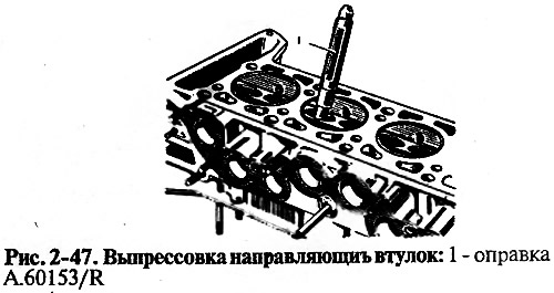
To replace the two guide bushings of the intake and exhaust valves of cylinders No. 1 and No. 4, unscrew the two studs securing the camshaft bearing housing, as they interfere with the installation of the mandrel.
Press in the guide bushings with the retaining ring on until the ring stops against the plane of the cylinder head.
After pressing, ream the holes in the guide bushings with reamers A 90310/1 (for intake valve bushings) and A.90310/2 (for exhaust valve bushings). Then grind the valve seat and bring the width of the chamfer to the desired dimensions as indicated above.
Oil deflector caps for guide bushings
At valve stem seals, rubber peeling from fittings, cracks and excessive wear of the working edge are not allowed.
When repairing the engine, it is recommended to always replace the oil seals with new ones.
It is recommended to replace damaged valve stem seals with the cylinder head removed so as not to bend the valve stems. To press on the caps, use the tool 41.7853 4016.
Valve levers
Check the condition of the working surfaces of the lever mating with the valve stem, with the camshaft cam and with the spherical end of the adjusting screw. If nicks or marks appear on these surfaces, replace the lever with a new one.
If deformation or other damage is found on the lever adjusting screw bushing or on the screw itself, replace the parts.
Springs
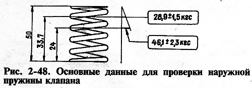
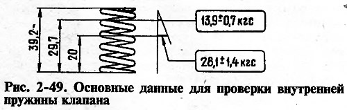
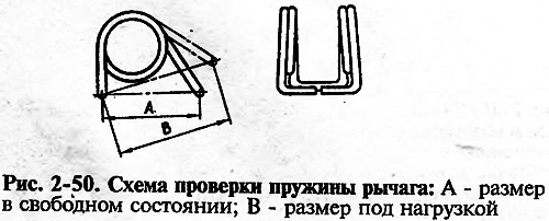
Make sure that there are no cracks on the springs and that the elasticity of the springs has not decreased, for which check the deformation of the springs under load (pic. 2-48, 2-49, 2-50).
For lever springs (pic. 2-50) size A (free spring) should be 35 mm, and dimension B under load 51-73.5 N (5.2-7.5 kgf) - 43 mm.