
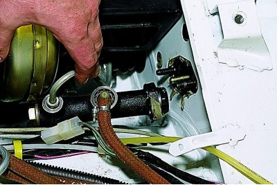
We remove the clutch master cylinder from the studs without disconnecting the tube and hose.
In the cabin, disconnect the wires from the brake light switch and the pusher of the vacuum booster from the brake pedal (see Removing the vacuum brake booster and adjusting the free play of the brake pedal).
Removing the instrument cluster (see Removing the instrument cluster).
We mark the location of the wires on the contacts of the ignition switch.
Disconnect the wires from the ignition switch.
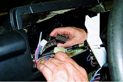
In the socket of the instrument panel, disconnect the three connectors for the steering column switch (You can identify these connectors by moving the stalk harnesses on the bottom of the steering column).
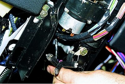
Disconnect the mount to the body of the steering shaft bracket (see Removing the steering column).
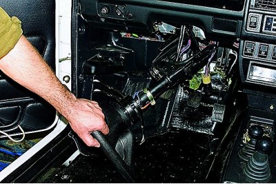
We lower the steering column with the steering wheel to the floor of the cabin.
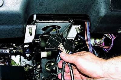
We remove the pads of the wiring harnesses of the steering column switch from the hole in the cross member of the instrument panel.
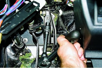
head «at 13» unscrew the four nuts securing the brackets of the pedal assembly and the vacuum brake booster to the front end shield of the body.
At the same time, on a VAZ-21214 car, by unscrewing the two nuts of the right fastening of the brackets, we remove the throttle actuator pedal (see Removing the throttle cable and pedal).
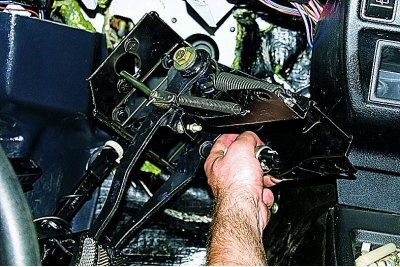
We take out the pedal assembly by turning it relative to the lower cardan joint of the intermediate steering shaft.
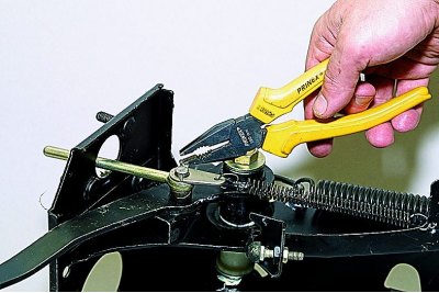
Pliers remove the cotter pin from the hole in the clutch pedal pin.
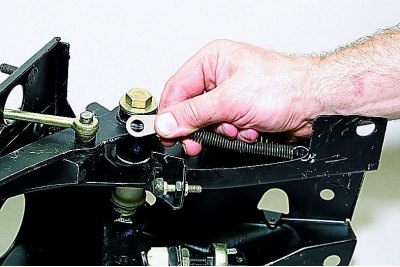
We remove the plate with the release spring from the pedal finger.
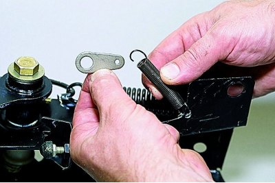
Disconnect the plate from the spring..
... and remove the spring.
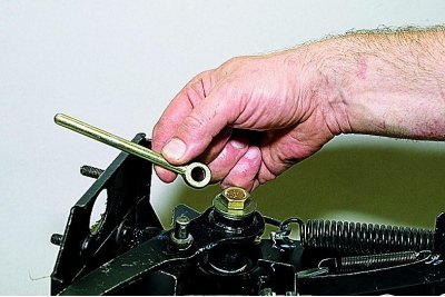
We remove the pusher of the master cylinder of the clutch release drive from the pedal finger.
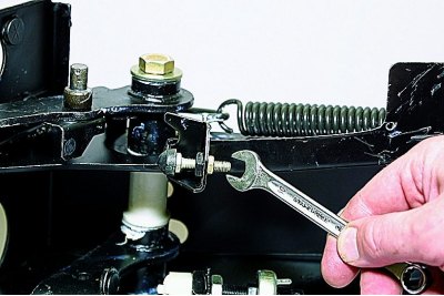
key «on 10» Loosen the clutch pedal locknut.
With the same key, we turn out the limiter..
...and take it off.
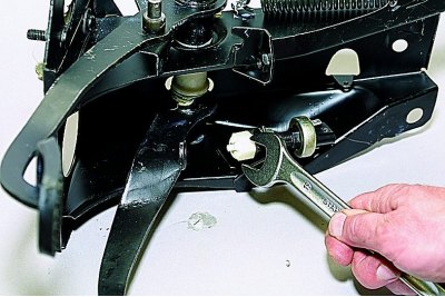
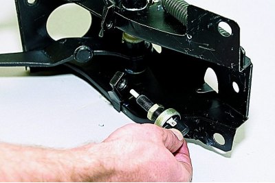
key «at 19» turn off the brake light switch buffer..

...and take it off.
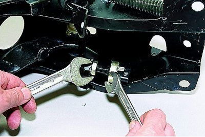
holding key «at 14» stoplight switch, key «at 19» unscrew the locknut.
Unscrew the brake light switch from the hole in the bracket.
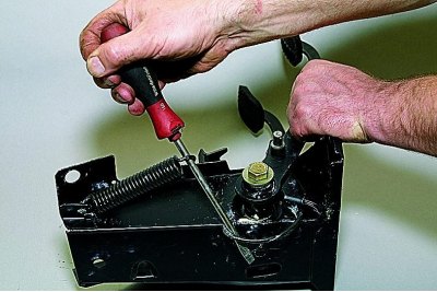
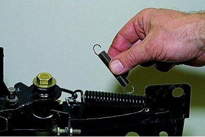
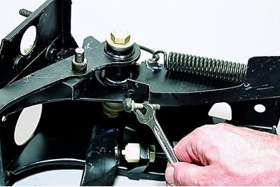
Prying with a screwdriver, disconnect the clutch servo spring from the hook.
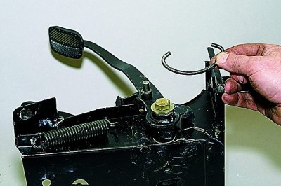
Taking the hook..
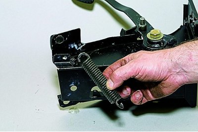
...and a spring.
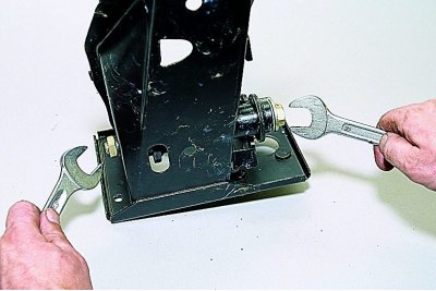
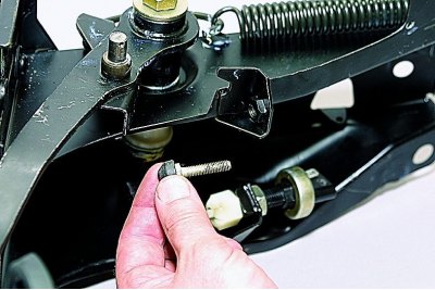
Two keys «at 19» unscrew the nut of the bolt-axle of the clutch and brake pedals.
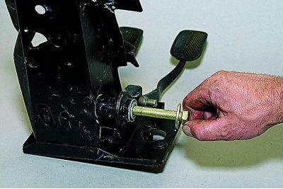
We take out the bolt with the washer.
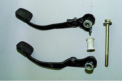
Pedals, bolt-axle and spacer.
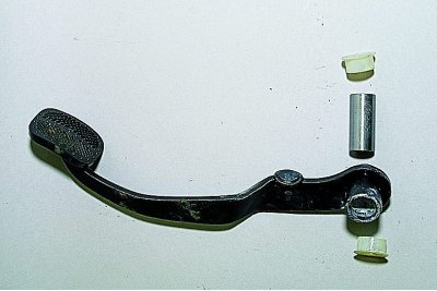
The boss of each pedal has an internal (metallic) and two external split (plastic) bushings.
We assemble and install the pedal assembly in the reverse order. Before assembly, we apply Litol-24 grease to the pedal bushings, the ends of the springs and the junctions of the pushers with the pedals.
When installing the clutch master cylinder, we insert the pusher into the cylinder piston seat, put the cylinder on the studs and fix it with nuts.
Helpful Hints
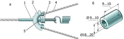
Parking brake adjuster: 1 - front parking brake cable; 2 - adjusting nut; 3 - locknut; 4 – a back cable of a parking brake; 5 - piece of tube
Increasing the ability to adjust the parking brake
If the thread stock on the front parking brake cable end is used (as shown in fig. A), you can choose a piece of a suitable tube (pic. b) and put it on the tip under the adjusting nut. Now the possibility of adjustment will increase.
Washer for parking brake cable
If the parking brake stops «hold», the cause may be the parted tabs of the bracket holding the rear cable sheath. In this case, to fix the cable sheath in the bracket, you can use a slotted washer, which should be inserted between the bracket and the sheath bushing. The slot of the washer should be directed «against» slots in bracket.
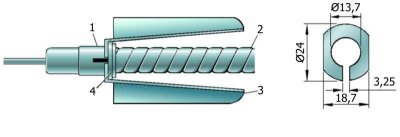
Rope attachment: 1 - bushing; 2 - shell; 3 - bracket; 4 - additional washer