
Defective shock absorbers
Due to the fact that wheel suspensions consist of a large number of parts, respectively, there may be a significant number of reasons that cause noise and knocks. To make it easier to understand this set, we highlight the most famous.
Once on the road with potholes and bumps, you begin to experience an unpleasant feeling that the bottom of the car is about to break through and the rebound rubber buffers installed on the rear axle beam will penetrate into the car. Such associations arise when shock absorbers fail. Their main task is to dampen vibrations, but they can only perform their functions under normal operating conditions. No shock absorber can withstand fast driving on a broken road. Shock absorbers especially get when driving on a bad road is also accompanied by heat. Shock absorbers - hydraulic, and liquid MGP-10 in them, compressed by a piston (without taking into account the high ambient temperature), heated almost to a boil. When overheated, the shock absorber fluid partially loses its qualities, and the efficiency of vibration damping decreases.
Often due to faulty shock absorbers, there are «breakdowns» car suspension. At the same time, the load-bearing parts of the body (spars, mudguards, racks) are deformed. If you do not pay attention to all this, over time it will be possible to detect cracks in the body pillars. In addition, having faulty shock absorbers, the wheels of the car lose the necessary contact with the road, which affects traffic safety. Hard shock absorbers and winter. It takes at least half an hour of driving for the fluid to start functioning normally. Therefore, in the first half hour of movement, try to spare the shock absorbers especially.
To determine the performance of shock absorbers, you must first check for fluid leaks. The current shock absorber has nothing to subject to further testing. So it is clear that it needs to be repaired or replaced. If a leak is not detected, a further check is carried out on a viewing ditch or overpass. Disconnect the lower end of the shock absorber and stretch, and then compress it. A faulty shock absorber will stretch in steps, with dips and not resist so much in certain sections of the course. Moreover, when stretching, it is necessary to apply five times more effort than when compressing.
To remove the shock absorber, only pliers and a 14 mm wrench are needed. After opening the hood, find the upper end of the shock absorber and, holding it from turning with pliers, unscrew the nut. While in the inspection ditch, unscrew the nuts of the shock absorber lower bracket bolts, remove the pin and pull the shock absorber through the hole in the lower suspension arm.
Shock absorbers of domestic and foreign production are installed on VAZ cars (Poland, SFRY, Japan). Not all shock absorbers installed on VAZ vehicles are subject to disassembly and repair. There are also non-separable structures (Japan). Only a few of the motorists decide to independently repair shock absorbers that can be disassembled. But since there are such craftsmen, we recall the procedure for disassembling shock absorbers, the causes of malfunctions and ways to eliminate them.
Before disassembly, the shock absorber is cleaned of dirt, washed and wiped dry. For disassembly, you need: a vise with sponges that would not crush the body or shock absorber eyelet and special keys that you need to make yourself (we hope that the one who took up the disassembly will also solve the key problem successfully). Having fixed the shock absorber in a vice, pull the rod all the way and unscrew the nut 18 (pic. 59) tank. Cylinder 16 with rod 1 and its parts are removed from the tank. After releasing the tank from the vise, the shock absorber fluid is poured into the vessel. To remove the compression valve from the cylinder, the valve body 11 is secured in a vise and the cylinder is slightly rocked.
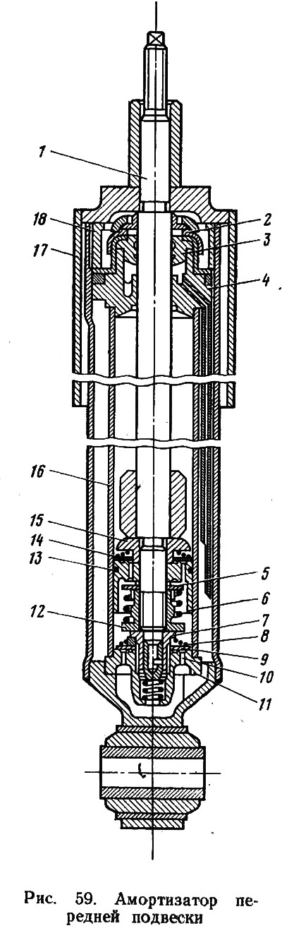
To disassemble the recoil valve, the stem 1 is clamped in a vice and the nut 12 of the recoil valve is unscrewed. They remove the piston 6 with valves, the guide bushing 4 of the rod, the stuffing box 3 of the stem, the clip of the 2 stuffing boxes, etc. Having disassembled the shock absorber, the parts are inspected, defective, those that failed to work are replaced with new ones, washed in kerosene and assembled.
There are certain requirements for some details:
- the valve disks and the bypass valve plate must not be deformed, and the bypass holes 10 must be free from contamination. Non-flatness of the plate is allowed no more than 0.05 mm;
- the working surfaces of the piston, piston ring 13, guide bushing 4 of the rod, cylinder 16 must not have burrs that could impair the performance of the shock absorber;
- valve springs must be intact;
- oil seals should be replaced during any repair.
The frill is performed in the reverse order, taking into account the following nuances: the recoil valve nut is tightened with a torque of 9.8–13.7 N·m, and the reservoir nut with a torque of 68.6–88.2 N·m.
The assembly of the compression valve assembly is carried out as follows: two discs 0.15 mm thick are installed in the valve body 11, then the throttle disc 5, the valve plate 9 with the protrusion down, the spring 8 and the nut 7. The assembled valve is inserted into the cylinder. A correctly assembled assembly should have a free play of the plate of at least 1 mm. When assembling the stem assembly, it is important to prevent damage to the plate 14 of the bypass valve on the end face of the restrictive plate 15, so as not to reduce the resistance of the shock absorber during rebound.
After getting acquainted with the shock absorber device, it will be much easier to understand the cause of a particular defect, which means it will be good to know what needs to be done.
Here are the main causes of shock absorber leaks:
- wear or damage to the stuffing box 3 rod. He is being changed;
- ingress of mechanical particles on the sealing lips of the stuffing box. In this case, the shock absorber fluid must be filtered;
- shrinkage or damage to the sealing piston ring 13. It is changed;
- nicks, risks on stem 1, complete wear of the protective coating. Such a rod is changed, and with it the stuffing box and fluid. MGP-10 liquid is poured into the shock absorbers in the following quantity; in the front 105-115 cm3, and in the rear 175-185 cm3. It should be remembered that shock absorbers normally perceive only the fluid recommended by the factory. Only in extreme cases, the liquid MGP-10 can be replaced with liquid AZH-12T or AZH-16A;
- loosening the nut 18 of the tank. The nut is tightened.
If the shock absorber weakly resists when checking it, the cause must be sought in: leakage of the recoil valve or bypass valve; breakage or occurrence of ring 13 in the piston groove; insufficient amount of liquid; scuffing on the piston or cylinder; fluid contamination.
When the shock absorber starts to knock and this knock is not caused by wear of the rubber bushings in the eyes and poor tightening of the shock absorber fastening nuts, then «guilty» there is a deformed casing 17, a loose nut 18 of the tank, a deformed rod 1 or a cylinder 16.
Worn rubber parts and hinges
The rubber bushings on the shock absorbers can be easily removed. To change the silent block, i.e., the rubber-metal hinge, you need a special device manufactured by the Odessa plant of radial drilling machines and put on sale.
It is more difficult to replace or repair the ball joints of the upper and lower front suspension arms. In the first and second cases, they must be removed. The upper ball joint is not lubricated during operation. This is ensured by the use of Teflon fabric impregnated with thermosetting resin as a bearing.
Given that the housings of ball bearings and hinges are one-piece, their condition can only be assessed by determining the presence of backlash between the ball and the bearing surface. However, one should not rush to conclusions. Tactics for finding the true source of extraneous knocking can be as follows:
- holding the upper edge of the front wheel with both hands and shaking it, determine the presence of a noticeable backlash;
- put the car on stands. It is desirable that they be 280-300 mm high;
- adjust the clearance in the hub bearing of the wheel under study, thus eliminating one unknown;
- in the moment, «when the assistant shakes the suspended wheel, determine the presence of backlash by alternately touching the hinge or silent block with your hand.
It must be remembered that the allowable clearance between the ball and the bearing of the upper support should not exceed 0.8 mm.
To determine the further performance of the ball joint, it is necessary to rest the hub on one of the supports (height 280-300 mm), clean the area where the conical plug is located from dirt, unscrew it and use a caliper to determine the actual distance from the support housing to the end of the ball pin. If this distance is more than 11.8 mm, the support must be changed or repaired. Removing the upper or lower ball joints can sometimes be very difficult. Neither the device recommended by the factory nor such an ancient and proven tool as a hammer helps.
The most effective was a device made by one of the motorists (pic. 60, a). It equally successfully copes with both the upper and lower ball joints. Before installing fixture (pic. 60b) necessary:
- securely fix the car;
- unscrew the three nuts securing the dismantled support to the lever and the self-locking nut from the ball pin.
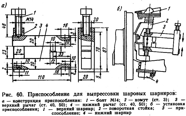
When dismantling the lower support, the self-locking nut must initially be unscrewed only by 2-3 threads, otherwise the thread may be broken.
If you are performing the operation for the first time, you need to be on the alert, because sometimes at the moment of separation of the parts, cotton is heard and the upper support can jump up sharply. To avoid surprises, it is advisable to tie the upper support to the eye of the swivel stand with a wire before pressing it out.
Most motorists who repair a car on their own have successfully mastered the repair of the upper ball joints. The experience of a motorist from the city of Kursk allows you to try your hand at repairing the lower ball joint (pic. 61), if necessary (i.e. there is no way to purchase a new one) and if it makes sense (i.e. body 2 is intact and all other elements are not very worn out: ball pin 1 and anti-friction insert 4).
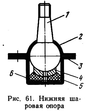
The sequence for restoring the lower ball joint is as follows:
- drill out the welding spots in the body 2 and separate it from the clip 3;
- place a washer 6 made of sheet oil-resistant rubber 1.5–3.5 mm thick, depending on the degree of wear of the hinge, under the rubber thrust bearing 5;
- assemble the hinge by connecting both parts of the body by welding.
Before installing new or repaired supports, do not forget to fill the space between the support and the rubber boot with ShRB-4 or Li-tol-24 grease.
Searching for knocks in the front suspension (pic. 62), it is advisable to carefully examine the condition of the levers 1.8 themselves and the crossbar 4. For a number of reasons, cracks can form on them, the presence of which is fraught with major troubles. In addition to shock absorbers 3 and ball bearings 2 and 10, knocking in the suspensions can create an anti-roll bar 7. It rarely happens, but it does happen. The fastening of the rubber pads 6 is weakened, or they wear out. In the latter case, they must be replaced.
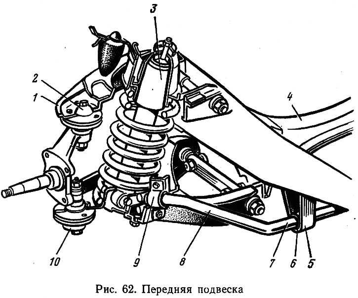
Considering that the need to replace one or more anti-roll bar pads usually occurs after 100 thousand kilometers, the main difficulty lies in unscrewing the nuts that fasten the clip 5 and 9 of the pad to the front suspension arm or side member. Do not break into an open door, make the nuts pliable with a kerosene compress. Having unscrewed the nuts of the cushion cages that are to be replaced, we can assume that 75% of the work has been done. Freed from the attachment, the stabilizer, due to its elasticity, will independently separate from the lower arm.
If one of the extreme pillows is to be replaced, then a new rubber pillow with a bracket is put on the end of the stabilizer that has moved away from the lever and, pressing the end of the stabilizer to the lower lever, tighten the nuts. When it is necessary to replace the pillow of one of the middle brackets, proceed as follows: unscrew the fastening nuts of the extreme and middle brackets; remove the extreme bracket with a pillow; tighten the middle bracket with a pillow; install a new pillow in the middle bracket, ensuring that the protrusion of the pillow enters the hole in the bracket; put the middle bracket with the pillow assembly on the stabilizer. To greatly facilitate your work, it is advisable to clean the stabilizer from dirt and bumps, and then lubricate it with soap. For the final completion of the operation, it remains only to fix the middle bracket, put on and fix the last one.
Increased clearances or wear of the wheel bearing. How to deal with this defect is described above.
The wheel balance is broken or the front suspension spring is broken. In this case, it is advisable to contact a service station, since high-quality balancing of the wheel can only be done on a special stand. To remove and install the spring, special equipment is also needed. Handicraft in this case is unacceptable. It must be remembered: the compressed spring of the front suspension is a high-energy accumulator.